
Tianhuangping pumped storage power plant is the first large-sized pumped storage project in the east China area, with a capacity of 1800MW made up of six 300MW units. The first unit (No. 1) was put into operation on 30 September 1998; No. 2, No. 3, No. 4 and No. 5 were running by the end of December 1998, August 1999, December 1999 and the start of March 2000, respectively, and the last unit was put into operation in December 2000.
Since the operation of the first unit in 1998, Tianhuangping has contributed greatly to peak load and trough regulation, frequency regulation and emergency standby, etc. for the east China power system and has played a key role in safe and stable operation of the whole power grid. In 2005, the project was also awarded a National Golden Medal at the 11th Excellent Engineering Design in China award and the 9th Excellent Engineering Survey in China.
Design details
Project description
Tianhuangping pumped storage power plant is located in the town of Tianhuangpingin in Anji county, Zhejiang province, 175km away from Shanghai and 34km from the 500kV Pingyao substation of the East China power grid (which covers Zhejiang, Jiangsu, Anhui and Shanghai), near the load centre of the power system. Annual power output is 3.014 x 1BkWh for water pumping (power for load trough filling) and 4.104 x 1BkWh, for pure daily regulated pumped storage. Two 500kV outgoing lines are linked with Pingyao substation to undertake the tasks for peak load regulation, load trough filling, phase and frequency regulation and emergency standby.
The Tianhuangping plant has the largest capacity for a single unit and highest head for a single stage reversible unit of any similar projects existing or under construction in China, and is also the largest in the whole of Asia. Asphaltic concrete facing was used for the whole 285000m2 upper reservoir basin, it has a concrete lining water conveyance system with maximum static water pressure for 680m head, a gravity drainage tunnel set in an underground power house, and features three circuits of dry type 500kV cable as its outgoing line – a first for China.
Natural condition at the dam site
The upper reservoir, water conveyance system, underground power house caverns, switchyard, etc. are located on the left bank of Daxi creek, where there is a huge mountainous body with landform head of about 700m. The natural head between the bottom of the upper and lower reservoir is about 590m; mean head was 570m after creating the dam, maximum cross head for power generation is 610.2m, the horizontal distance between the two reservoirs measures around 1km, the ratio between water conveyance system and mean power generation head is 2:5 and topography is steep.
With regards to precipitation issues, the annual rainfall in the dam site area is 1849.6mm with long-term annual mean flow of 24.5Mm3. The annual flow of a dry year with fixed rate of 99% is about 10Mm3 with inflow to the lower reservoir enough to compensate for evaporation and leakage loss, and there is no flow source for the upper reservoir. The 100-year flood of the lower reservoir is 536m3/sec, 1000-year flood is 859m3/sec and probable maximum flood (PMF) 1280m3/sec. The long-term mean temperature at the dam site is 13.8°C.
Stratum in the project area is mainly of volcanic rock from the upper series of the Jurassic system, such as liparite-tuff, porphyry, quartz-porphyry and granite-porphyry. The geologic structure is not developed and fault scale is small. The Q4 stratum has no badness action and the seismic intensity is less than 6º.
Layout and design of main structure
Project layout
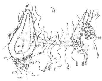
Tianhuangping pumped storage power plant is formed of an upper reservoir, lower reservoir, water conveyance system, 500kV switchyard and underground power house caverns. The ventilation and access shaft and 500kV cable shaft, equipped with elevator, serves as a vertical linking passage between the underground power house caverns and the 500kV switchyard and control building, and the access tunnel to the power house serves as a horizontal passage between the underground power house caverns and the ground surface (see Figures 1 and 2).
Upper reservoir
The upper reservoir is at a depression of a branch of the Daxi creek with a catchment area of 0.327km2 without natural inflow to the reservoir. No spillway is set for the upper reservoir. The main dam is at the south of this depression and four sub-dams are located in the east, north, west and southwest. The main dam is a 72m high rock and earthfill structure, with upstream slope 1:2 and downstream slope 1:2.2. The designed maximum storage water level is at el. 905.2m, with corresponding storage capacity of 9.192Mm3; dead water level is at el. 863m, with corresponding dead storage capacity of 0.3797Mm3. Operation depth is 42.2m, daily water level fluctuation at normal operation conditions 28.42m, dam crest elevation is el. 908.3m and dam crest length is 2km.
When constructing the upper reservoir, treatment of completely-weathered soil on the bottom and dam base became a concern. In order to solve this problem, asphaltic concrete facing was adopted, which has a higher resistance for uneven settlement on the upstream of main dam and sub-dam, bottom and bank of reservoir. The asphaltic concrete facing is of simple structure with three layers: top is the closing layer (2mm thick), middle is the impervious layer (100mm thick) and the bottom functions as the levelling and bonding layer (80mm-100mm thick).
Lower reservoir
The lower reservoir is located in the middle reaches of Daxi creek and the catchment area is 24.2km2 upstream of the dam site. The dam of the lower reservoir is formed from a reinforced concrete faced rockfill dam (CFRD), whose characteristics are an upstream slope of ratio 1:1.4, a downstream slope of 1:1.3, dam crest elevation measured at el. 350.2m, and a maximum dam height at dam axis of 92m.
The cushion layer of the dam body is 100cm with a larger infiltration coefficient (K=5×10⁻²cm/sec~10-3cm/sec), without structure joints for reinforced concrete facing plinth. The purpose of decreasing the cushion layer thickness, increasing the infiltration coefficient and relaxing the upstream slope was to keep the stability of facing at large daily fluctuations of water level, and decrease unfavorable conditions for water raising.
The designed maximum storage water level of the lower reservoir is el. 344.5m, corresponding to storage capacity of 8.5956Mm3. Dead water level is at el. 295m, which corresponds to dead storage capacity of 0.5748Mm3; operation depth is 49.5m, daily water level fluctuation at normal operation condition measures 44.8m, and the reservoir length is about 2km. The side-weir type spillway is set on the left bank with a curved and inclined flip bucket for power dissipation, and the construction diversion tunnel on the right bank serves as water supply and reservoir empty tunnel. In addition, one sand-stop weir is set on the reservoir tail to head off the bed load into the reservoir.
Water conveyance system
The water conveyance system links the upper and lower reservoirs and is formed by the intake/outlet of the upper reservoir as well as the accident maintenance gate shaft, inclined penstocks, manifolds, horizontal branches after manifold, tailrace tunnel and maintenance gate shaft, intake/outlet of upper reservoir, etc. Length is 1415m in total.
Each intake/outlet of the upper reservoir links with one inclined shaft (inner diameter 7m) and is lined with reinforced concrete. Each inclined shaft links with three horizontal branches (inner diameter 3.2m, high pressure penstocks) through the reinforced concrete manifold. The inner diameter of the penstock near the side-wall upstream power house is transitioned to 2m to connect with the inlet spherical valve of the unit. The surrounding rock of the high pressure pipe bears whole or partial hydraulic pressure, the steel pipe is within 8m near the side-wall upstream power house and has an open-type tube design and the whole inner hydraulic pressure is taken on by steel plate.
Rock overburden thickness in the steel lined section meets the necessary requirement for maximum pressure. Apart from the steel lined section near the power house, the whole water conveyance system (including manifold) is lined by reinforced concrete with a maximum inner water pressure of 680m head, which is uncommon for projects such as this.
The intake/outlet of the upper reservoir has a bank-type shaft and the intake/outlet of the lower reservoir adopts a bank-type slope mode. The vortex-proof beam and current distribution pier are used for the intake/outlet of both upper and lower reservoirs, and the plane and section diffusion angles are optimised to reduce head loss at the intake/outlet and let water flow in and out smoothly.
In order to reduce external penstock and manifold water pressure, two sets of drainage systems are put in place: one is formed by vertical and horizontal drainage gallery and vertical drainage holes inside the gallery 35m above the manifold and penstock, to drain seepage upstream of the water conveyance system in surrounding rock and decrease penetration pressure; the other drainage system is directly arranged on the outer wall of the penstock in order to drain seepage along the interface of steel lining and concrete to decrease external pressure on the penstock.
Underground power house, mechanical and electrical equipment and switchyard
The underground power house adopts a tail arrangement. Its caverns include main and auxiliary plant hall, main transformer hall, busbar tunnel, tailrace gate tunnel, 500kV cable shaft (also serving as ventilation and access shafts) and the access tunnel to the power house, all covered by liparite-tuff rock.
The main and auxiliary plant hall is 198.7m long, 22.4m wide and 47.73m high, the unit section is in the middle, auxiliary plant is at the south end and the erection bay is located at the north end. No.1 unit bay is 27m long, and the other five unit bays are each 22m, whereas the erection bay is 34m long. The main power house is set with a crane beam on the rock wall. The main transformer hall and tailrace gate tunnel is parallel to the main power house hall and arranged on the downstream side. The main transformer hall and power house hall is linked with six busbar tunnels and one main transformer shipping tunnel. The underground caverns are not all lined with reinforced concrete, only with bolt-shotcrete support, mesh spraying or anchor bar locally.
Favourable landform is used to arrange 1.6km of long gravity drainage tunnel for the underground power house – no special unit leakage and maintenance and drainage devices are necessary. All water is drained by gravity to stop the risks of flooding the power house and ensure safe power house operation in case of any drainage equipment fault or power outage, and at the same time to save the amount of power consumed by water drainage devices.
Six vertical shaft, single stage reversible pump-turbines are used in the power house, with 526m net head at turbine mode, rated output 306MW, maximum output 338MW, and maximum power input at pumping mode 336MW.
The motor-generator is a vertical shaft, suspended-type, air cooled reversible synchronised motor, with a rated capacity at generating mode of 333MVA and motor mode of 350MVA. The excitation of unit adopts a static frequency converter system. The pump mode uses static frequency converter and back-to-back starting. The plant selects six 500kV, 360kVA, three-phase double winding, forced oil water cooled transformers, to link with six motor-generators to form three combined units, and the main transformer is housed in an underground cavern.
A 500kV switchyard is set on a platform at el. 350.2m on the left bank above the intake/outlet of the lower reservoir, with total area 208m x 35m; this switchyard is on the middle of the platform; control building, 35kV step-down substation and diesel oil generator room are on both ends. The 500kV distribution device selects SF6 gas isolated system, six bays, by outdoor arrangement. The control building is located on a platform at el. 350.2m.
Key design techniques
About 20 years passed between a dam site being selected and Tianhuangping pumped storage power station being complete. Much has been achieved in this time, including:
•A set of engineering geology methodology for pumped storage projects was explored, resulting in the reasonable selection of project scale and the layout of the upper and lower reservoirs. The natural topographical and geological conditions were used to the project’s advantage, with the ratio of water conveyance system and mean generating head achieving 2.5; plus a reasonable water passage structure was designed and the actual unit operation synthesised efficiency above 90%. According to the specific condition of the power station, the unit utilisation rate has raised, by improving the flood regulation of the lower reservoir.
•Project design was able to use favourable geology and high ground stress conditions, and the upstream water conveyance system adopts reinforced concrete lining. Manifold receives maximum static water pressure of 680.2m head and dynamic water pressure 887m head; the structural design of main and auxiliary plant is reasonable, with large rigidity for vibration resistance, and vibration research of the power house has been carried out. Crucially, the gravity drainage system in the underground power house has improved operation safety.
•The asphaltic concrete facing is adopted for the whole reservoir basin (a 285,000m2 area) and its operation shows the advantage of having high adoptability for uneven base settlement, and cracking can be repaired easily and quickly. The completely-weathered soil with high water content and low natural bulk density is used fully to build the main dam and sub-dam of the upper reservoir to solve the problem of a shortage of embankment material for the upper reservoir area. The lower reservoir uses a concrete faced rockfill type dam, and excavation material is used for the dam embankment.
•The science and technology study on ‘Parameter and Structure Selection of High Head and Large Capacity for Pumped Storage Project Unit’ was completed. After meeting the prerequisite of operation reliability and flexibility, a single busbar with three sectional connections at 500kV voltage side is used to optimise the design of the main connection and to reduce the investment of mechanical and electrical equipment even more. A cross-linking polyethylene (dry type) used is for the 500kV outgoing cable for the first time; the motor-generator adopts the radial ventilation without extra fans; 500kV circuit breaker has no switching resistance; and the digital relay with art at the beginning of the 1990’s is used for unit and transformer
Project finance
The project adopted ICB, financed by the World Bank. Foreign funds are used mainly for overseas procurement of mechanical and electrical equipment and international bidding for partial civil works. Local funds were provided by the State Development Bank and East China Power Group Company, along with Shanghai, Jiangsu, Zhejiang and Anhui provinces. LCB was adopted for all civil works except the asphaltic concrete facing of the upper reservoir, where ICB was used. ICB was also used for the procurement of pump-turbine, motor-generator, main valve, computer system, 500kV main transformer, 500kV GIS HV device and 500kV HV cable.
Author Info:
Zhang Weimin, President/Professor, and Zhang Chunsheng, Chief Engineer/Professor, East China Investigation and Design Institute under China Hydropower Engineering Consulting Group Co, Hangzhou, China
| Award winning |
| Tianhuangping pumped storage power plant was awarded a National Golden Medals at the 11th Excellent Engineering Design in China and the 9th Excellent Engineering Survey in China in 2005. |


