MHI is has designed a version of its Advanced PWR for the US market, with a particular focus on achieving economies of scale. The thermal power is the same as its Japanese APWR but electrical output has been increased by improving efficiency.
After a hiatus of more than 20 years, during which there has been no nuclear new build in the USA, a new era – the nuclear renaissance – is upon us, with a number of new nuclear units planned. Even though nothing has been built in the USA for the past couple of decades, Mitsubishi Heavy Industries (MHI) has nevertheless continued to design, manufacture and construct nuclear units in Japan. It has also designed an advanced PWR (APWR), of larger capacity than conventional 4-loop plants. Construction of two such APWRs is planned in Japan (Tsuruga 3 and 4) and licensing is underway.
The design of the APWR is based on conventional 4-loop plant technology, which has amassed significant operating experience in Japan, scaled up to achieve the higher electrical output. But in addition to adopting these proven technologies, modifications are also introduced into the APWR to improve economy, safety, reliability, operability, and maintainability. And, with the reawakening US market in mind, MHI has developed a larger-scale version of the APWR, aiming at higher electrical output and improved economics, by modifying some design features of the APWR without increasing core thermal output.
Design features
Table 1 shows the main specifications of the Japanese APWR, the US-APWR and, for comparison, a typical current US 4-loop PWR.
To take advantage of economies of scale, the electrical output of the Japanese APWR is raised to 1538 MWe by increasing the capacities of the core and main components. To further reduce operating costs (fuel and O&M), an additional increase in electrical generating capacity is achieved in the US-APWR, to the 1700 MWe class. This is thanks to an increase in plant thermal efficiency of about 10%, while thermal output is kept at 4466 MWt, exactly the same as the Japanese APWR. The overall plant efficiency increase is achieved by raising efficiencies in the steam generators (SGs) and the turbine system.
Large core, low power density
The APWR and US-APWR fuel load consists of 257 assemblies of 17×17 type fuel. The core diameter is maximised taking into account the limitations arising from the stability of horizontal xenon oscillations, with the aim of maximising core capability.
The APWR uses 12ft long fuel assemblies, as employed widely in Japanese PWRs. The US-APWR employs the same design but extends the effective fuel height from 12ft to 14ft to reduce the specific power of the core while keeping the same reactor vessel height (Figure 1). This low power density design not only provides a larger thermal margin, but also allows a 24 month operation cycle, with a greater than 2 batches refuelling strategy, resulting in a reduction in uranium requirements of about 16% compared with a conventional PWR, when the effect of improved thermal efficiency (as described above) is also taken into account.
With the adoption of a larger core in the APWR and US-APWR, related components, eg reactor vessel, reactor coolant pumps etc, are also in turn enlarged relative to those used in a conventional 4-loop plant.
High thermal efficiency
For the US-APWR MHI placed considerable emphasis on increasing thermal efficiency to allow higher electrical output, resulting in an operating cost that is about 10% lower than the APWR.
In the steam generators of the APWR and US-APWR, smaller but more effective separators, giving a 10-fold reduction in moisture carry-over (to 0.01%), are employed. Also, tubes of 3/4-in outer diameter are used. The result is a more compact steam generator, but at the same time achieving better performance (Figure 2).
In addition, the steam generator design for the US-APWR (type 91TT-1) has a 30% greater heat transfer area – further contributing to higher efficiency. This is achieved by adopting a triangular lattice configuration with narrow tube pitch. As a result, even though the heat transfer area has been increased, the diameter of the 91TT-1 steam generator body is slightly smaller than the 70F-1 steam generator used in the APWR.
At the same time, reliability is further increased by adopting TT690 alloy for the tubes and a 10-point support anti-vibration bar (AVB) to shorten the support span relative to the conventional 6-point support.
The APWR steam turbine uses fully 3-dimensional reaction blades, which have an excellent performance record, especially for nuclear turbines, and a low-pressure last blade in the form of a 54 inch ISB (Integral Shroud Blade) to achieve high efficiency and improved reliability. The 54 inch last stage blade has been subjected to vibration and load tests to demonstrate its performance and reliability. For the US-APWR, the length of the blade will be increased to around 70 inches for larger output.
Neutron reflector
The neutron reflector (NR) developed for the APWR/US-APWR aims at structural simplification to improve reliability and neutron economy. The neutron reflector, as shown in Figure 3, consists of stacked ring blocks made of stainless steel instead of the baffle plates, former plates, and neutron pads of the today’s PWR. The ring blocks are aligned by alignment pins, and all blocks are fastened together with eight tie rods. The neutron reflector consists of only about 50 parts including bolts and nuts, while the baffle structure of a current PWR employs more than 2000 bolts. The new design not only increases the reliability of the structure but also reduces the inspection burden for bolts located in the high fluence region. The neutron reflector also contributes to reducing the neutron fluence to the reactor vessel by 60% relative to that in a conventional 4-loop PWR.
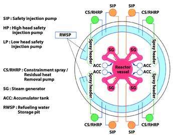
Four-train DVI system
The APWR/US-APWR employs a 4-train direct vessel injection (DVI) system, as shown in Figure 4. Such a configuration increases redundancy and independence between trains, and thus enhances safety and reliability. The 4-train DVI system also helps to achieve simplicity and compactness in the safety system by enabling a reduction in the capacity of each train, from 100% to 50%, and eliminating inter-connecting piping between each train. The 4-train system can be maintained “on line” thus avoiding a big concentration of maintenance work load during periodic tests.
As for emergency AC power supplies, the APWR, reflecting the high reliability of the Japanese grid, employs two diesel generators, while for the US-APWR, the emergency power supply system is modified to 4-train configuration to enhance reliability. The advanced accumulator (described below) allows some relaxation of the start-up time requirements for the emergency generators, and thus gas turbine generators may also be appropriate for the emergency AC power supply system of the US-APWR.
Advanced accumulator
The safety system of the APWR/US-APWR consists of an optimised combination of active and passive components.
The advanced accumulator is a passive component employed to enhance both safety and economics through its injection flow characteristics and elimination of the low head injection system.
The flow characteristics of the advanced accumulator, as compared with a conventional system, are shown in Figure 5. By adopting a flow damper mechanism, the advanced accumulator supplies water at a high flow rate in the early stages of a LOCA, and provides a supply of relatively low flow rate even at the later stages in accordance with requirements. As shown in Figure 6, when the water level is above the top of the standpipe, water enters the flow damper through both inlets, at the top of the standpipe and at the side of the flow damper. It thus injects at a high flow rate. When the water level drops below the top of the standpipe, the water enters the flow damper only through the side inlet and thus the flow rate falls.
The injection function of the advanced accumulator and its flow damper have been confirmed in 1/2 scale verification tests at the actual plant operating pressure.
Full digital I&C
Advanced main control boards and consoles, as shown in Figure 7, and a fully digital I&C system, including that for reactor protection, is employed in the the APWR/US-APWR to improve the man-machine interface and increase reliability.
An advanced alarm display system that dynamically prioritises alarms has been developed and applied to the APWR/US-APWR to avoid information overload and to facilitate plant state identification. The prioritised alarms and their associated process parameters are provided in the graphical representations of plant systems displayed on the large panel, categorised according to a 3-level colour coded system.
An emergency operation support system is provided for the APWR/US-APWR to assist operators in the event of abnormal and accident situations that threaten plant safety.
The advanced main control boards and consoles together with the full digital I&C system have been tested according to a rigorous V&V (verification and validation) test plan. In addition, the overall operability of the system under normal and accident conditions has been tested using a prototype console connected to a full scale plant simulator.
The utility operating crews from several power stations participated in the validation, and the workloads associated with the advanced and the latest conventional system compared. This showed that the advanced system reduced the physical and mental workload by about 25% and the estimated potential human error also by around 25% relative to the conventional system.
Construction performance
Based on MHI’s experience of constructing 23 PWR plants in Japan over the last 30 years, the construction strategy for APWR/US-APWR aims to further increase the amount of work done in the factory relative to that done at site. There will be increased use of prefabricated piping and component modules and steel/concrete composite structures will be used inside the containment, with a “super heavy duty” crane deployed for installation.
Construction work will be further optimised and managed by making use of an information management system based on 3D CAD/CAM, enabling a seamless interface to be achieved with the design effort.
As a result of these measures, the APWR/US-APWR is expected to be constructed in a considerably shorter time than previous plants, particularly when the large installed capacity is taken into account.
Furthermore, the US-APWR will have a building volume per kWe that is about 30% less than the latest 4-loop PWR in Japan. A major contributor here is that safety equipment is located in each quadrant of the reactor building, very close to the reactor coolant system loops, reduce both building volume and piping quantity.
Figure 8 shows the configuration of the
US-APWR.
Talking to the NRC
Mitsubishi Heavy Industries plans to apply for design certification of the US-APWR by US Nuclear Regulatory Commission (NRC), and some pre-application review meetings have already been held.
Figure 1. Cutaway of US-APWR reactor vessel Figure 2. Cutaway view of high performance steam generator Figure 3. Neutron reflector of the APWR Figure 4. Configuration of emergency core cooling system Figure 5. Flow chacteristics of the advanced accumulator, compared with a current 4-loop design Figure 6. How the flow damper works Figure 7. Advanced main control board and console Figure 8. Cutaway of the US-APWR plant