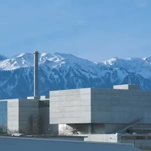
The new facility, in Ludvika, Sweden, will allow long-term testing of DC transmission components rated at 800 kV. It is well known that Thomas Edison wanted the first American distribution system to be DC, but was over-ruled. Maybe he was right all along, because it is generally agreed that the next major T&D challenge is UHVDC (ultra high voltage direct current), a step up to transmission systems rated at 800 kV which will make it viable to produce electricity in underpopulated regions, such as exist in China, India, Brazil and Africa, where vast hydropower resources remain untapped, and carry it economically to population centres.
Going to higher transmission voltages and DC has three advantages that are self evident. HV takes a smaller land area (narrower corridor) and lower I2R line losses. A UHVDC link 2000 km (1200 miles) long is 30 % cheaper to build and operate, says ABB, partly because it reduces electricity losses by 30 % compared to 500 kV DC or 800 kV AC lines.
It also, of course, has no associated electro-magnetic radiation and a negligible oscillating magnetic field. ABB, which admittedly has a vested interest, say that it also costs less in other ways. Their studies, summarised in Figure 1, indicate that for a sufficiently long line at sufficiently high voltage, 800 kV DC costs more in substations than other formats but that this is more than outweighed by cheaper line costs and lower losses.
The site will operate at 850 kV DC, and will test equipment such as transformer bushings, wall bushings, a bypass breaker, a surge arrester, smoothing reactors, voltage dividers, RI-capacitor, disconnector, an optical link, post insulators and a a transformer prototype. Testing will consist mainly of subjecting the equipment to 850 kV for 6-12 months or maybe longer. And as most of the equipment is to be tested in the open air there will automatically be a weatherproofing test for rain and airborne grit as well for the outdoor properties of polymeric insulation.
The site is located within STRI, the Swedish Transmission Research Institute. This is an independent technology consulting company and accredited high voltage laboratory assigned by ABB to construct and operate the new facility. It is owned by ABB (50%), the Swedish TSO Svenska Kratnät, (25%), Vattenfall (12.5) %, and the Norwegian TSO Statnet (12.5%). It already has a development centre with an extensive high voltage laboratory.
The market for UHV
800 kV DC seems likely to account for a significant part of world growth in power transmission capacity over the next ten years. China and India are set to be the main users of the new technology as they seek to secure reliable power supplies and exploit sources, particularly hydro, that are located far from the load centres.
In these two countries, the demand for energy is growing dramatically. Every year, China has to install new generating capacity equivalent to the entire installed capacity of Sweden. This means exploiting large reserves of hydropower in the west of the country. However, the power is needed in the east and south, 1500 to 2000 km away. China is currently planning to build one 800 kV DC line per year over the ten year period from 2007, with a capacity of between 5000 and 6400 MW per line.
India has plans to expand hydropower in the north-eastern part of the country. As in China, the demand for power is far from the source, so here too the power will need to be transmitted as far as 2000 km. India is currently planning to build one 800 kV DC line every two years over the next decade, with a capacity of 3000 to 6000 MW per line. There are more distant plans too to install 800 kV lines in southern Africa and Brazil: in Africa from Congo to South Africa (Western corridor) and in Brazil in the Rio Madeira area.
Up to now, 500 kV DC has been used for long-distance transmission of electric power, over distances of as much as 1000 kilometres. With the introduction of 800 kV DC it will be possible to transmit power over distances up to 3000 km with acceptable transmission losses. Moreover, the power flow in a DC line can be readily controlled. This stabilises the transmission network and helps prevent cascading outages.
Technological step
The last voltage increase in HVDC systems occurred 20 years ago when ABB built a transmission line rated at 600 kV for Brazil’s Itaipu hydroelectric power plant – a world record. So for ABB, who pioneered HVDC systems more than 50 years ago, this facility represents a third major contribution to the development of HVDC technology. In 1954 it delivered the world’s first HVDC commercial installation, a link between the island of Götland and the Swedish mainland. In 1997 it introduced HVDC Light, a transmission technology capable of delivering full reactive and active power control.
This latest step forward has been a long time coming, mainly because it depended on the success of basic research in a number of areas. First, the development of new materials for insulators in an outdoor environment. Using a higher voltage also implies a greater gap to ground in order to isolate live parts. For one hundred years, insulators to provide these gaps have mostly been made of porcelain, but the past 15 years have seen the development of new plastics that have made it possible to abandon porcelain, primarily in favour of silicone rubber. This material has been shown to possess very favourable properties for outdoor insulation.
Second, advanced computer-aided design tools for three-dimensional field calculations, primarily for transformer design.
Third, refined measuring techniques using advanced laser technology to determine the characteristics of insulating materials and systems.
Fourth, advanced control systems that control the entire installation. This calls for extremely high computing power, exploiting state-of-the art computer processors and information technology to the limit. At the test site the Mach2 system (developed in-house by ABB) is employed.
The 800 kV project
A development project aimed at raising the voltage to 800 kV was started in the mid-1990s, but the basic research needed to achieve it was not completed. While the project was in progress, the market lost interest and the project was abandoned. However the basic technological developments described above gradually became available, and about two years ago extensive product development started, most of it at ABB’s facility at Ludvika, backed by its central research laboratory at nearby Västeräs.
The central features of the the project to date have been as follows.
• With up to 9000 MW being carried on a line, extreme reliability is obviously essential, so a completely new station design has been produced to make it possible to meet these requirements. It is required that a line fails not more than once in 25 years. Increased availability is achieved by extensive sectioning of both the main circuit and the auxiliary systems. In addition, all control and safety systems are duplicated, as are auxiliary systems such as auxiliary power and emergency battery systems.
• New types of all the high-voltage devices subject to DC have been developed and fitted with newly developed polymer insulating materials. Examples of such devices are potential dividers, bypass switches, radio interference suppression capacitors, disconnectors and post insulators.
• One of the main aims of the project was to develop a new transformer and a new bushing for 800 kV. The foundation for this was the basic research described above. Prototype bushings were produced and type-tested. For the transformer, a mock-up was built to simulate the parts of the transformer subject to high DC voltages. Figures 2 and 4 shows the transformer and wall bushing during tests.
• New models to calculate the required insulation gaps have been developed. Extensive tests were carried out at extremely high, previously untried voltages. Figure 3 shows a discharge arc more than ten metres long, at over 2 million volts during an insulation gap test.
• The Mach2 control and protection system has been developed further to satisfy the extreme reliability demands.
• A new thyristor and thyristor valve have been developed to handle the increased voltage and current.
• Finally, all critical devices must undergo endurance testing, at elevated voltage extending over a year, to verify the long-term characteristics of components.
Financial and other benefits
Two main driving forces justify the use of 800 kV HVDC. First, the installation, including the power transmission line, is significantly cheaper for the customer. Second, this technology takes up considerably less space, an argument at least as important as the simple capital cost.
There are three main aspects to the financial evaluation, namely power line losses, the investment cost of the line, and the investment cost for the converter station and associated AC switch gear. Figure 1 illustrates the cost differences between 765 kV AC, 500 kV DC and 800 kV DC. The example is for a 2000 km line to transmit 6000 MW.
There are also environmental advantages, in addition to the narrower corridor required, stemming from lower losses and the weaker magnetic fields of a DC line. So HVDC lines, unlike AC lines, can easily satisfy the stricter magnetic field requirements increasingly being enforced in the West.
Economic aspects
Since the early twentieth century three-phase alternating current has been the dominant option for the transmission of electric power over long distances. Figure 5 shows the history of increasingly higher voltages, as the transmission of more power over greater distances became desirable and feasible.
But since the introduction of 765 kV lines in 1968 there has been no further increase in the transmission voltage of commercial systems. A number of trial lines operating at I000 and 1200 kV have been built, but to date operators have stayed with 765 kV as the highest voltage used.
For AC systems, the transmitted power is limited by reliability and voltage stability requirements. Today, the usual capacity is 600 MW for 400 kV links and 2000 MW for 765 kV systems. On long 400 kV+ transmission lines (more than 300 km) it is normal practice to install capacitors along the line, in addition to the switchyards and junctions, to maintain the voltage and reduce losses.
The development of HVDC for power transmission purposes began in the mid 1950s (Figure 6). Line losses are significantly lower for DC. For a 2000 km link, line losses for 800 kV DC are about 5 %, while the corresponding losses for 765 kV AC are double, at about 10 %.
For the transmission of comparable amounts of power, the cost of a power line is lower for DC. A 2000 km HVDC transmission line rated at 6000 MW needs one power line with two suspended conductors. An equivalent AC link operating at 765 kV requires three power lines each with three suspended conductors. However HVDC requires converter stations at each end of the power line, so short power lines using DC are relatively expensive.
Figure 1. Total evaluated costs in MUSD for 765 kV AC, 500 kV DC and 800 kV DC lines transmitting 6000 MW over 2000 km. Figure 2. One of the main aims of the project was to develop a new transformer and a new bushing for 800 kV. Prototype bushings were produced and type-tested. Figure 3. New models to calculate the required insulation gaps have been developed, involving extensive tests at extremely high, previously untried voltages. The picture shows a discharge arc at over 2 million volts to test the insulating air gap. These fFigure 4. A mock-up to simulate the parts of the transformer subject to high DC voltages. The photograph shows the transformer during tests. Figure 5. Development of 3-phase AC transmission voltage levels. Figure 6. Maximum voltage for DC transmission, 1953 to 2010.