
The Ågesta nuclear power plant was Sweden’s first commercial reactor and was part of the Swedish reactor development programme in the 1960s. The reactor is located in an underground rock cavern, close to Stockholm. It is heavy water cooled and moderated pressurised vessel reactor, which was used for electricity production and district heating. It was in operation between 1964 and 1974, with a peak output of 80MWt and 12MWe.
Since 1974, Ågesta has been in ‘care and maintenance’. Fuel and heavy water were removed from the site in the 1970s. The decommissioning plan is to dismantle the radioactive portions of the plant over 3-6 years. New systems, including lighting and ventilation, and new equipment were installed prior to the start of decommissioning and dismantling, which commenced in summer 2020. The first large items to be demolished and disposed of were the loading machine and the heavy water tanks of which approximately 80 per cent was cleared, sent for melting at an external facility and recycled.
Among the components left in storage positions after the permanent shutdown of the Ågesta reactor were 27 coarse control rods. Previous decommissioning studies did not consider the technical complexity, cost or time of managing these components in detail. Dealing with these coarse control rods was the third large decommissioning project to be carried out.
The control rod management challenges
Ågesta contained 30 control rods in all, 27 coarse control rods and three fine adjustment control rods. The coarse control rods are 5m long and weigh approximately 400kg each. They have a 3m long extension containing the neutron absorber, in which the highest levels of dominant persistent radionuclides are found. The absorber is of sandwich construction, with inner and outer tubes made of stainless steel and a mid-layer comprising silver, indium and cadmium. The isotopes which provide the highest contributions to dose rate are Ag-108 and Co-60.
Additional investigations were made during preparations for decommissioning, including the measurement of dose rates from the control rods. These indicated dose rates one order of magnitude higher than indicated previously, ie a maximum surface dose rate exceeding 1000mSv/h and up to 30mSv/h at a range of 1m. There were no suitable ‘ready to use’ concepts for on-site management, transport, or segmentation and conditioning of the Ågesta control rods.
A feasibility study was initiated in 2018 to investigate possible options for managing the control rods. The result was a comparative analysis between the main options identified — off-site segmentation or in-situ segmentation. In early 2019, Vattenfall’s Business Unit Nuclear Decommissioning (BU.ND) decided to proceed with in-situ segmentation.
“Since there were no ‘ready to use’ concepts we had to design a method and several tools ourselves,” says project manager Linda Ekstrand, Vattenfall’s project leader for the control rod segmentation at Ågesta.
Developing an in-situ segmentation option
In order to minimise the volume of waste that must be deposited in the Swedish repository for long-lived radioactive waste, activated parts had to be separated from the rest of the control rods. The absorber part was segmented in-situ with remote-controlled equipment, to enable manual handling of the remaining part.
The equipment developed to handle the movement, segmentation and packing of the control rods consists largely of modules built up using proven technology. The aim was a simple and robust methodology and reliable equipment. The modules were to some extent modified before being mounted on site.
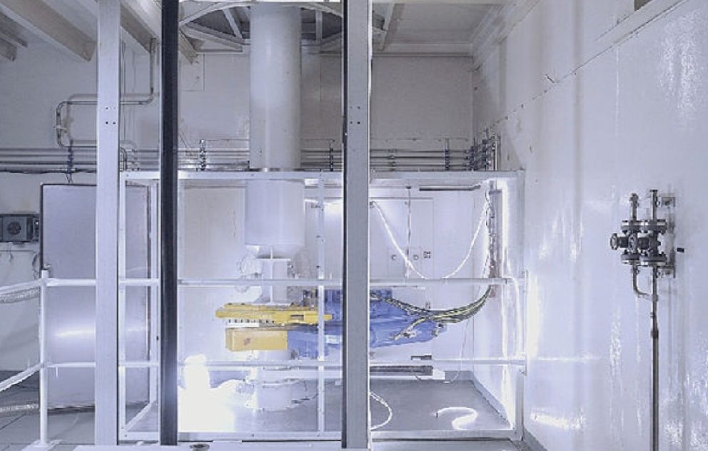
It was essential to address ALARA in the design and planning stages. Manual handling of the control rods would be avoided as much as possible, and the segmentation equipment was placed and arranged so that other operations in the plant would be affected as little as possible. The equipment was designed and painted to minimise the potential for secondary surface contamination so that it could be easily cleaned. Robotic control cabinets and scissor hydraulic units were placed outside the cutting working space to facilitate repair or restoration.
“We performed the work deep down in the facility, far away from us and other ongoing work, with additional shielding coming from the several floor layers in between the equipment and other personnel. The process was remote controlled with cameras and computers from a station in the reactor hall,” says Ekstrand.
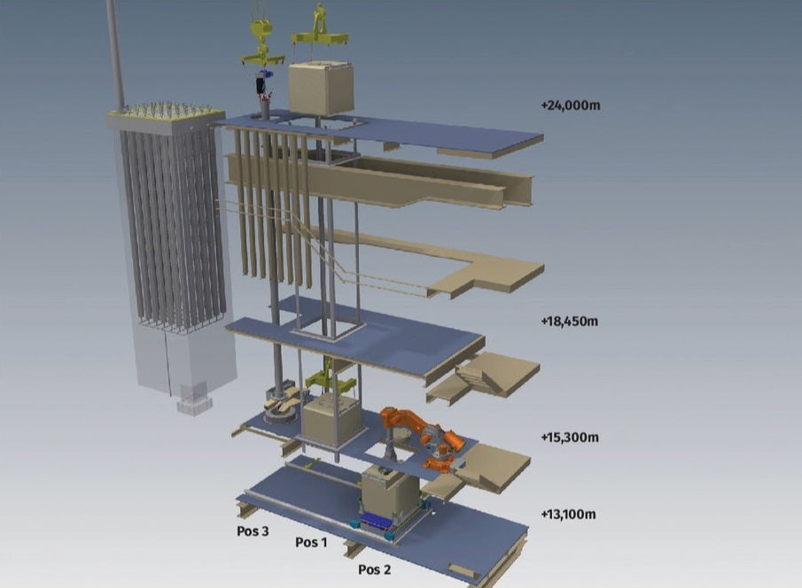
The solution for moving the control rods was a 6m radiation protection tube attached to a specially-made lifting yoke, suspended from the plant’s main traverse. This was combined with a 1t telfer, which was used to lift the rods up into the shielded tube. During lifting, a docking ring was designed to be placed on the position with the control rod, which stabilised the heavy radiation protection tube and ensured that the telfer could be hooked into the control rod safely. A camera and a dose rate probe were placed in the opening, for monitoring when the control rod was hoisted up. The radiation protection tube with the control rod could then be moved just a few centimetres above the floor to the shaft where it was lowered towards the scissors.
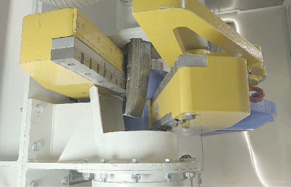
Powerful alligator scissors were mounted for vertical clipping (model DTX600-11kW-Xtra Torque with cutting power of 240t). This method was chosen to minimise heat generation and the creation of secondary waste. To keep the spread of contamination in a confined space, but still be able to monitor the cutting via camera, an enclosure of steel frames and polycarbonate was mounted around the scissors. A ventilation exhaust was mounted on the installation and connected via a filter box to the general ventilation.
Segments of the absorbers were collected in an 80-litre barrel placed in a single-hole concrete container. The barrel was reinforced with an additional inner drum for shielding against radiation and damage from the cut segments. The waste packages were tightly docked below the scissors to avoid radioactive contamination on the outside of the concrete mould. A lifting table on a remote rail car was used to manoeuvre waste packages to the docking position below the scissors (Pos 3), to the position for opening and closing the waste packaging (Pos 2), and to the central position
(Pos 1), where the concrete mould could be lifted up and down to the reactor hall.
It was realised early on that the compression and length of the cut segments were important considerations for overall volume reduction. Here the use of the scissors had another advantage, as it both pressed together and cut off the segments. Tests of gasketing with different segment lengths were done, using an inactive dummy and the tests indicated that segment lengths of about 125mm would be enough to house two full absorbers in an 80-litre barrel.
Locking the lids onto the 80-litre barrels also offered challenges. The lids have a locking mechanism that is released by pressing a plunger placed in the middle of the lid. For this, a custom-made tool with an electrically controlled ball screw was used that was mounted on a used industrial robot. The robot was programmed with pre-determined movement patterns to be able to mount the three lids: for the inner barrel; for the 80-litre barrels; and for the outermost concrete cap. Three laser pointers and a camera were used to fine-tune the robot’s position between these steps.
Testing
It is important that a design concept that looks suitable in theory or on paper is verified in reality. A key to ensuring the equipment was functional and optimised has been to assemble and test the equipment off-site before transporting it to Ågesta. This was done at a local workshop, which was also commissioned to manufacture and modify parts of the equipment as necessary.
After installation at Ågesta, inactive tests of all the constituent parts were again carried out. Documentation and risk analyses were supplemented, and CE marking was made by moving machines.
Performance
On 15 December 2020, the first active control rod was cut. With functional controls completed and the control rod in position above the scissors, the cutting of absorbent could be initiated and 20 minutes later there were 24 segments in the barrel. However, unlike in the inactive testing, a longitudinal bend was created in the rod, which meant that the remaining part of the control rod could not be lifted up again. As one of the least active control rods had been selected as the first active test, the lower part could be cut manually and the remaining control rod returned to its original position. After this, a minor modification of the equipment was made. The narrow section that sat above the scissors was removed prior to cutting and this turned out to be enough to handle the bend. The length of the segments was also slightly reduced to ensure a sufficient degree of packing.
It was also found that the lower part of the control rod, after segmentation, had a higher dose rate than expected — about 10mSv/h. The method and equipment for handling the remaining part had to be developed. Moreover, a fully-extended absorber was a prerequisite for segmentation in the scissors and, pending restart, work was done on releasing the absorber locking mechanism on the control rods. This was done with a simple mechanical tool that was mounted on the guide rod head. In several cases, the locking mechanism offered stubborn resistance before releasing.
In March 2020 the remaining 26 control rods were lifted, cut and replaced in their original position without additional problems. Nuclide specific activity measurement was done with a CZT-probe on each concrete package.
Once all the control rods’ absorber parts were segmented, the remaining parts of the control rods could be segmented using a metal band saw. Here, too, standard equipment could be combined with custom-made equipment to solve the task of sawing, lifting and sorting to different waste fractions. The activity levels of the different neutron-induced material fractions were assessed separately and later combined in the same containers before transport.
The amount of loose activity released from the absorber during cutting was less than had been prepared for, but the enclosure around the scissors fulfilled its function well and kept any freed contamination enclosed.
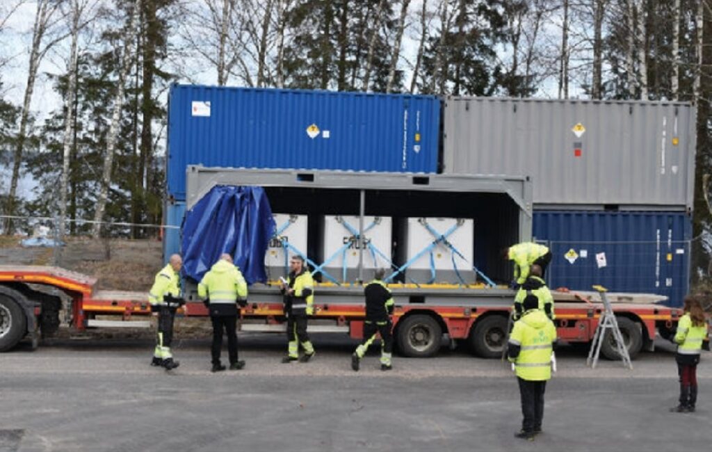
All parts of the rods have been transported in the shielded containers to SVAFO’s interim intermediate-level waste storage facility in Studsvik. SVAFO has reloaded all barrels into larger containers that can hold five 80 litre barrels. The control rod dummy unit will be donated to the Technical Museum in Stockholm, along with some other artefacts from Ågesta.
Overall assessment
By using a tailor-made arrangement of proven equipment and technology it was possible to develop an innovative technical solution to enable the in-situ segmentation of control rods. This enabled the work to proceed safely in a challenging workspace with limited access and constraints on equipment volume and logistical areas.
To proceed from the initial design concept to delivery of an optimised functional technical solution, entailed considerable up-front work and adaptations to mitigate risks. This development was driven by Vattenfall in close cooperation with designers and manufacturers.
“While the specific concept developed may be uniquely applicable to the specifics of control rod segmentation at Ågesta, the overall approach which combines standard equipment and technology to deliver a unique bespoke solution may offer a useful model for projects elsewhere,” says Ekstrand.
This article first appeared in Nuclear Engineering International magazine.


