
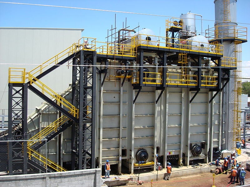
The typical large HRSG (heat recovery steam generator) used for utility power generation is a counter-flow heat exchanger with thousands of boiler tubes. These are spread between the various modules that form the interface at which the waste heat from the gas turbine exhaust is recovered and converted into steam for power generation. Cold feedwater enters the back (stack) end of the HRSG and flows against the exhaust flow direction through the economiser, evaporator, and superheater modules to exit as superheated steam.
The HRSG can have from one to three pressure levels depending on size and specific plant requirements. Each pressure level requires separate economiser, evaporator, and superheater modules. Typically, triple-pressure units will include reheat modules as this further improves cycle efficiency. Supplementary firing using burners installed in the gas path is also often included in the design. These allow the amount of heat in the exhaust gas to be increased, thereby raising steam production.
The tubes in the different modules are made of various carbon and alloy steel grades. The choice of material is driven principally by design temperature and pressures, although the cost is also a consideration if more than one steel grade would meet the design service requirements.
HRSGs have undergone substantial changes in design over the past 30 years as the technology has matured, starting from small single-pressure units driven by aero-derivative gas turbines to today’s large triple-pressure units with reheat running steam pressures in the high-subcritical region, not to mention the various once-through designs.
Besides fundamental design differences, modern HRSGs are also subject to a wider range of duties in power applications. Baseload operation was normal for earlier HRSGs, but today’s deregulated electric power market requires that many new large HRSGs cycle or operate on flexible duty.
The relatively simple design and less severe operating conditions relative to radiant boilers running with coal or oil create a more benign environment for HRSG heat exchanger tubes. Nonetheless, failures do occur, and tube failure rates naturally tend to increase as plants age. In addition, the cycling operation regimes that are being imposed on plants are driving higher failure rates and changes in the failure modes.
Another factor affecting the evolution of tube failure modes and frequency is the demanding steam cycle process conditions encountered in the newer large combined cycle plants.
When Tetra Engineering published the first edition of its Tube failure diagnostic guide, in 2004, the authors anticipated the higher pressures and temperatures that emerging HRSG designs would impose on tubes. The result would be a greater risk of high-temperature damage due to creep, corrosion fatigue and damage due to stresses that result from differential thermal expansion. Tetra Engineering’s observations over the two decades since have largely confirmed that prediction.
Insights from the database
Based on company projects, Tetra Engineering has gathered statistics on tube failures in HRSGs from over 100 different sites in North/South America, Europe, the Middle East, and Asia. The HRSGs under consideration encompass a diverse range of models and sizes from nearly every manufacturer.
The data are drawn from approximately 24 years of Tetra Engineering projects. Whilst not an exhaustive or complete accounting of every relevant project in that period, it does provide a useful indication of the frequency of occurrence of failures by HRSG location and by mechanism.
Failure locations
Tube failures occur in all heat exchanger modules, from the cold-end economisers to the hot-end superheaters and reheaters. Tubes in the hot-end steam-carrying components are the biggest problem area. These are exposed to higher temperatures and pressures, making them more vulnerable to degradation through mechanisms such as creep and thermal fatigue compared to their cold-end counterparts.
Damage mechanisms
The nature of service (baseload or cycling), fuel type and water quality will also influence the frequency of occurrence for a given damage mechanism. Mechanisms driven by operation include creep, fatigue, creep-fatigue, corrosion, corrosion-fatigue, tensile overload and flow-accelerated corrosion (FAC). Fabrication defects are another source of failures, the incidence of which is also influenced by operating conditions.
- Creep failures are due to the degradation of the steel microstructure from tensile stresses and temperatures outside the design envelope over longer periods. It is a well-documented cause of damage in boiler and piping pressure parts and represents 12% of failures in the assessments.
- Fatigue failures (23%) are generally caused by excessive temperature gradients that typically occur during operating transients such as start-up and load changes.
- Creep–fatigue (4%) occurs in components experiencing both creep degradation and cyclic stresses. Failures occur at tensile stresses that are lower than would be required if either degradation mechanism acted alone.
- Corrosion in its various forms (such as cold-end surface corrosion or under-deposit attack) represents 19% of the failures.
- Corrosion–fatigue (4%) is the result of the combined action of alternating or cycling stresses and a corrosive environment. It should be noted that fatigue failures identified in some of the root cause assessments could include a corrosion component driving crack growth, hence it may be more relevant to combine fatigue and corrosion fatigue into a single class of failures.
- FAC failures (9%) are caused by accelerated dissolution of the protective internal magnetite layer, leading to progressive wall thinning as base metal reacts to form new magnetite continuously.
- Fabrication defects (12%) vary from incorrect welding procedures to incorrect material installation. These failures are avoidable with even modest surveillance during manufacture.
- Tensile overload failures (12%) result from inducing stresses greater than the material’s ultimate tensile strength, primarily through rapid contraction caused by quenching or rapid cooling of tubes.
The tube location (and consequent environment) influences the susceptibility to each damage mechanism.
Materials
The frequency of failures by a material also reflects how common the material is across the HRSG fleet. For example, based on field observation T23 is not a commonly used material in HRSGs, hence the fraction of failures involving this material would in any case be small.
While materials do not inherently cause failures, of course, a poor material choice, with materials deployed in the wrong locations may accelerate failure mechanisms.
For example, carbon steel tubing in areas that are exposed to the risk of FAC is more susceptible to wall thinning, due to a lower resistance to wear caused by this mechanism. This explains why, after repeated FAC failures, plant operators often specify repairs that use low-alloy steel (T11, T22, T91) tubes. These materials contain chromium and molybdenum, which improve the resistance to magnetite dissolution and significantly reduce the risk of tube wall thinning.
Repairs after FAC tube failures can entail partial replacement of affected tube sections or even installation of completely new modules. HRSG designs from some OEMs have also evolved to use low-alloy materials in critical sections such as the upper tubes of the LP evaporators. Unfortunately, this partial “solution” while less costly than extending use of low-alloy materials to further locations, is often imperfect, with failures occurring in adjoining carbon steel sections after some years of operation.
Significant reductions in the creep life of grade 91 components have been observed. These have often been attributed to incorrect heat treatment resulting in an undesirable material microstructure.
Prevention of tube failures
For the most part, tube failures can be avoided by operating within the design envelope and by performing the appropriate O&M actions as specified in plant operating procedures.
As plants age certain additional actions may become necessary or more frequent, such as cold-end cleaning to remove excessive amounts of corrosive deposits on tubes or chemical cleaning to remove deposits in evaporators.
It is essential that the O&M actions include regular in-service and off-line (outage) inspections as well as the monitoring of HRSG process data at reasonable intervals. Effective inspection and monitoring are essential for preventing failures, as they enable the detection of potential issues before degradation leads to failure.
Tensile overload of reheaters provides an example of where effective monitoring can anticipate failures. Failures due to tensile overload of reheaters are typically a result of thermal shock incidents such as rapid cooling or quenching of the affected tubes; inadequate condensate draining or attemperator over-spraying are almost always the root causes. Ensuring manual drain valves are opened before start-ups, and attemperator spray/isolation valves are not passing are key to avoiding these types of failures.
Tetra Engineering has also noted that some plants lack flow sensors in the reheat and superheater spray loops; accessing this data could help prevent overspraying and subsequent thermal shock.
Inspections during outages can detect incipient cracks at the tube–header welds via non-destructive testing (NDT). Bowed tubes can also be an indication of excessive tensile stresses.
Another example concerns superheater tube creep failures. These are among the most frequently observed tube failures and are almost always attributable to high metal temperatures. Causes include non-uniform gas turbine exhaust gas flows, maldistribution of duct burner flames, burner firing with the low steam flow, poorly designed flow correction devices and side or centre baffle damage.
Visual inspection can identify any mechanical damage such as missing baffles, with accompanying NDT (hardness and surface replication) used to check for signs of creep degradation. If superheater thermocouples are installed by design, these can be used to track temperatures and provide input to creep life calculations. If not present, thermocouples can be retrofitted at a relatively low cost.
Finally, taking a tube sample for laboratory analysis is always an option to get a definitive reading on creep progression. This is ideally done after other data indicates that there may be a potential creep problem or after some longer period of operation (50k hours or more).
Conclusions
In summary, analysis of a data set constructed using a sizeable sampling of the tube failure mechanisms and locations identified in projects performed by Tetra Engineering over several decades shows that hot-end components, ie, superheater and reheater tubes, are the biggest problem area, with nearly half the failures investigated occurring in these tube locations.
This is consistent with the observed failure mechanisms, wherein creep, creep–fatigue and fatigue account for about 40% of the failures. The frequency of occurrence of these mechanisms and their propensity to occur in the hot-end components are consistent. Creep requires high temperatures and fatigue will be most common in components subject to high thermal stresses and thermal expansion movements.
The relatively low frequency of FAC failures is somewhat surprising in that it is often cited as a major factor in HRSG failures. It is important to note that the data set is representative only of the projects from which it was compiled. While these projects are relatively broad-based in terms of the type and age of plants, they should not be taken as a definitive assessment of the distribution and frequency of tube failures in all HRSGs.
This article also appeared in Modern Power Systems magazine.


