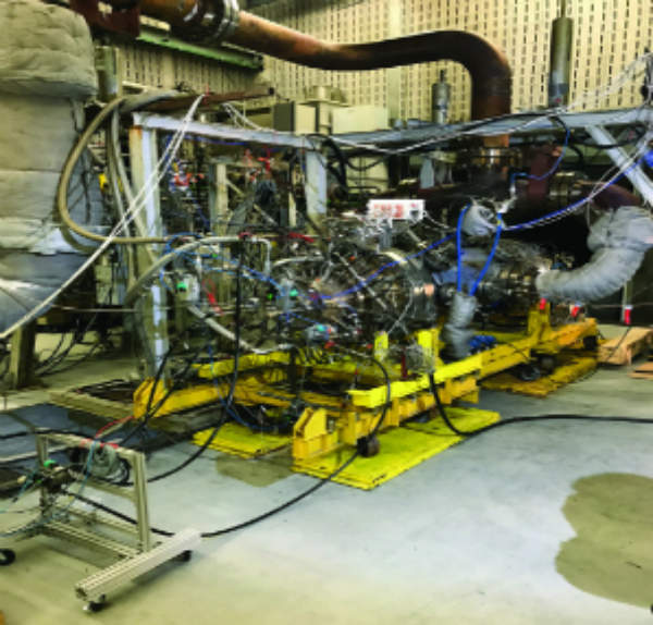
Testing time for FlameSheetTM
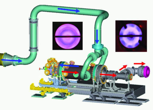
DLR FlameSheetTM flow schematic. Air is supplied to the test section in two locations from a single air feed pipe (blue arrows). A series of baffles is installed within the test section to simulate the engine air flow pattern to the combustor, as well as an engine-equivalent acoustic plenum (the latter being important for correctly simulating field engine combustion dynamics). The combustor is exhausted through a transition duct to simulate the engine acoustic boundary condition of the first stage vane (red arrows). The hot gases then travel through the water cooled exhaust duct (red arrows). A quartz window is located in the exhaust on the combust or centreline for observation of the flame. The exhaust turns 90 degrees at the quartz window before entering a back pressure valve (not shown), which simulates the back pressure effect of a turbine and is used to properly modulate combustion system pressure drop.