
Pump-turbine refurbishment at Blenheim-Gilboa
New York Power Authority’s (NYPA) Blenheim-Gilboa pumped storage power project was returned to service in November 2009 as part of a major overhaul that continues to progress. Work on the final phase of a US$135M life extension and modernisation (LEM) programme is scheduled for completion in June 2010.
The Blenheim-Gilboa pumped storage project is located in the Catskill Mountains in New York State, US. The 1040MW project is owned and operated by NYPA and first produced commercial power in 1973. It consists of an underground powerhouse with four Hitachi 260MW pump/turbine units, with one common penstock from the upper reservoir feeding four spherical valves. The gross head range on the units is 324.9-348.4m.
In 2003 NYPA began the process of upgrading and modernising the project’s four reliable but ageing pump-turbine units, with engineering and model testing of a new pump-turbine design. The first phase of construction began in September 2006 with the shutdown of the first unit and replacement of the pump/turbines and many major mechanical and electrical components. Since then, the process has been repeated three times, in the autumn of 2007, 2008 and 2009, with the third unit being successfully upgraded and brought on line in May 2009.
Three of the four pump-turbine generating units were also returned to service in November 2009 following the project’s shutdown in mid-September to permit replacement of a spherical valve on the final pump-turbine generating unit to be refurbished.
The project work scope includes the following major tasks:
• Refurbish the four pump-turbines, including replacement of the turbine runner with improved efficiency, increased capacity and reduced potential for cavitation of the turbine runner. The turbines will be upgraded so that each generator/motor will operate at up to approximately 318MVA at 0.9 power factor, or 286MW as a generator, and up to approximately 420,000HP, or 318MW at 1.0 pf motoring, at a temperature rise of 80°C.
• Replace one and refurbish three spherical valves.
• Dewater the upper reservoir to facilitate spherical valve replacement.
• Replace 17kV G/M air blast circuit breakers with new SF6 circuitbreakers.
• Replace the rotating, shaft mounted exciter with new static excitation systems.
• Replace starting motor (SM) liquid rheostat (LR) controls and instrumentation with a PLC-based system and switchgear to allow the use of any rheostat to start any of the four units.
• Replace/refurbish internal components of the liquid rheostat electrolyte tank.
• Refurbish the motor/generator including a thorough cleaning, re-insulating the field poles, re-rounding the stator and air cooler replacement.
• Installation of a new condition monitoring system for machine diagnostics.
• Replace the iso-phase heat exchangers/coolers.
• Replace the mechanical Woodward governor with a new electronic governor.
• Refurbish the G/M phase reversal switch.
• Replace the 285MVA generator step up transformers with 325MVA new 17KV/345kV, 325MVA transformers.
• Furnish and install a new transformer deluge system.
• Installation of new redundant generator protection relays.
The three units successfully completed to date have demonstrated significant improvements in pump and turbine efficiency, greater stable operating range, increased pump flows and increased maximum turbine output.
At the conclusion of the LEM programme it is projected that Blenheim-Gilboa will be capable of producing approximately 1160MW from the same amount of water.

Blenheim-Gilboa pumped storage project
Life extension for St. Lawrence-Franklin D. Roosevelt
The New York Power Authority (NYPA) continues to forge ahead on its life extension and modernisation (LEM) programme at the St. Lawrence-Franklin D. Roosevelt power project. In February 2010 NYPA had completed work on the 12th of 16 turbine-generators to undergo refurbishing as part of the US$281M initiative in New York state.
Refurbishment of the 13th turbine, which began immediately after completion of the 12th, is expected to be completed by August 2010. The programme is scheduled to run through to 2013.
The power authority began the St. Lawrence LEM programme in 1998 to replace or renovate the original major generating equipment in the power project, and improve the overall performance flexibility and efficiency of the facility which has operated continuously since 1958. The first new turbine was delivered in May 2001 for an in-service date of April 2002.
The work has required a highly coordinated effort involving nine major component manufacturers in achieving numerous installation milestones. Among the most significant activities has been the disassembly and removal of the turbines, the major component of the turbine-generator units, and the renovation of their turbine-pit locations to facilitate the installation of the refurbished units.
alstom Hydro USA was awarded two independent contracts in 1998 and 2004 to manufacture all 16 replacement turbines. The turbines are of two different designs, corresponding with the original equipment manufactured by Baldwin Lima Hamilton (BLH) and Allis Chalmers (AC).
At the time of St. Lawrence-FDR’s construction more than 50 years ago, no single manufacturer could meet the ambitious schedule for supplying the turbines. The responsibility was evenly divided between BLH and AC. Since 2007, the LEM programme has centred on the AC turbines, following the replacement of the eight BLH units.
Among the design advances in the replacement turbines is a more efficient shape for harnessing available water from the St. Lawrence River to generate power. The new turbines also use stainless steel instead of the carbon steel composite of the original equipment. Stainless steel is more resistant to corrosion and requires less maintenance, which will contribute to extending the life of the hydroelectric project.
Other elements of the LEM have included generator rewinding, installation of new switchgear, replacement transformers, and modernisation of protection and control systems.
The main features of the St Lawrence-FDR power project include the Robert Moses-Robert H Saunders dam, which stretches 975m across the St Lawrence River. The dam includes 32 turbine-generator sets with 16 operated by NYPA and 16 by Ontario Power Generation, producing 800MW for each utility. Over the decades of its operation, the St. Lawrence-FDR project has produced more than 340B kWh of electricity, which would be sufficient power to meet electricity demand in the US for one month.
Rebuilding Taum Sauk
Extensive refurbishment has taken place at the 408MW Taum Sauk pumped storage project in eastern Missouri. The plant started generating electricity again four and a half years after the collapse of the project’s upper reservoir dike in December 2005. The Federal Energy Regulatory Commission (FERC) authorised project owner AmerenUE to resume normal project operations at the project after completion of the rebuilding work in April 2010.
Paul C Rizzo Associates was hired by the dam’s owner AmerenUE to investigate the cause of the dam collapse, as part of a FERC requirement. Following substantial investigation and design, Rizzo concluded that substandard construction and instrumentation problems were partly responsible for the breach, earmarking the following points as key causes: stability failure; poor design; specification and maintenance of instrumentation and control systems.
It was determined by Rizzo that a repair of the existing dike was not technically feasible due to flaws in the original construction. Substantial areas of the existing dike were founded on residual soil. Additionally, few construction controls were utilised to control the gradation and character of the rockfill. Due to this and a number of other factors, a complete re-build of the upper reservoir was required.
The original construction of the upper reservoir was accomplished by flattening the top of Proffit Mountain, using rhyolite and excavated residual soil to construct the existing concrete face rockfill dike. After the breach, it was discovered that significant quantities of residual fines were mixed with the rock, and the rock itself had a wide range of particle sizes, ranging from gravel sizes to as large as 1.2-1.5m in diameter.
The new dam is founded on fractured rhyolite with deep weathering features, intrusive granites and weathered diorite dikes. A symmetrical RCC section will provide adequate factors of safety to meet FERC stability criteria considering the subscribed foundation conditions of the rock.
The new RCC dam is constructed along the same alignment as the original concrete faced rockfill dam. Since the upper reservoir is founded on top of Taum Sauk mountain, it has no watershed. The probable maximum flood (PMF) for the new RCC dam consists of the rainfall within the reservoir. Therefore, the hydrology and hydraulic criteria are limited to two major factors: the elevation of the crest of the new RCC dam, including freeboard; the capacity of the proposed overflow release structure (spillway).
The overall design basis was to rebuild the upper reservoir so it will have the same generating capacity as the original upper reservoir with a normal pool and overall gross head, as established in the FERC licence for the Taum Sauk plant.
The rebuilt reservoir project is currently the largest RCC dam in North America, and was recently named the recipient of the Award of Excellence in the Constructed Project during the US Society on Dams 2010 annual meeting and conference.

Taum Sauk: view of the RCC wall
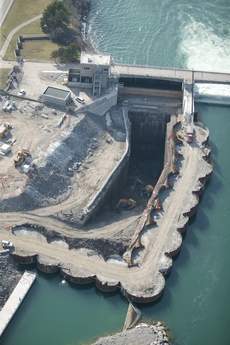
Niagara power tunnel
Ontario Power Generation’s Niagara tunnel project includes the planning, design and construction of a 10.2km long, 12.7m internal diameter tunnel to divert an additional 500m3/sec of water from the Niagara river to existing generating stations. The project will restore Ontario’s capability to effectively utilise the water allocated to Canada under a 1950 river water diversion treaty signed between Canada and the US.
When the new Niagara tunnel is in operation, the water it delivers will permit the existing Sir Adam Beck generating station to produce 14% more energy. This will increase average annual output by about 1600GWh, enough to supply 160,000 Ontario homes with hydro power.
The design/build contractor, strabag, is using the world’s largest hardrock tunnel boring machine (manufactured by The Robbins Company) to excavate the tunnel. Work got underway in September 2006 and by 4 August 2009 excavation had officially reached the halfway milestone.
However, in September 2009 planned maintenance work for tunnelling equipment was brought forward while a small rockfall was investigated and repaired. The incident, more than 3km along the tunnel well behind the TBM, happened in a stretch of tunnel that had previously suffered overbreak problems. Both rock and the lining fell in the accident but no-one was injured.
As of May 2010 the TBM had progressed to 6882m. The project was scheduled for completion in mid 2010 but due to the poor ground and tunnelling difficulties, this has been re-negotiated to the end of 2013.

Niagara project – intake channel excavation within the cofferdam
Efficiency improvements at Hoover dam
The Lower Colorado river basin has experienced the worst drought on record since the early 1900s. The 2074MW Hoover dam on the Colorado river between Arizona and Nevada, has continued to provide consistent water deliveries to Colorado river water users throughout this time. However as a result of this, lake elevation at Lake Mead behind Hoover dam is only at 44% of capacity, causing concern about loss of total generation capacity (at 76% -1688MW); loss of regulation capacity; increased rough zones; and increased maintenance (cavitation) concerns.
Efficiency and capacity improvements have been taking place at Hoover dam since 1998. The work has involved:
• Major overhauls of turbine components.
• Stainless steel wicket gates.
• Opening existing wicket gates beyond 100%.
• Unit controls modernisation.
• Wide head range turbine.
Work on the wide head range turbine got underway in April 2010, when Commissioner Michael L. Connor from the US Bureau of Reclamation (USBR) announced the award of a US$3.4M contract to andritz Hydro Corporation of North Carolina. This was for the design and manufacture of a new wide head turbine runner for generating unit N-8 in the Nevada wing of the Hoover dam power plant.
“The new turbines will allow the generating units to operate more efficiently over a wider range of head than the existing turbines do,” Connor said. “That will enable Hoover dam to generate power more efficiently as the water level behind the dam fluctuates between low and high elevations.”
The new runner is scheduled to be delivered to the dam in February 2012 for installation by USBR. If it performs as anticipated, USBR may exercise a contract option for additional runners for generating units N-6, A-1 (in the Arizona wing of the power plant), and N-5. The total investment in the new turbines will be approximately US$11.56M, and the additional runners would arrive at the dam in November 2013, 2014 and 2015, respectively.
There are 17 commercial units in the Hoover dam power plant – nine in the Arizona wing and eight in the Nevada wing. The existing turbines are designed, in general, to operate over a higher range of lake levels. At very low lake levels, operation of existing turbines becomes rough and inefficient.

Hoover dam on the Colorado River
Bear Creek remediation
The Tennessee Valley Authority (TVA) constructed the Bear Creek Dam in 1969 to provide flood control, recreation, water supply, and economic development benefits. The dam is located in Franklin County, Alabama, and is one of two dams in the Bear Creek Project. The structure consists of an earth dam, a concrete overflow spillway with a highway bridge carrying County Road 37 across the spillway and dam, an intake tower, lined tunnel, and an outlet structure. The dam is approximately 1200ft (366m) long at the crest and is 68ft (21m) high at the maximum section. The crest of the overflow spillway is at elevation 602 and the crest elevation of the dam is 618.
The dam is a homogeneous rolled fill embankment constructed from compacted residual soil. It is founded on karst rock consisting of the Mississippian age Bangor Limestone underlain by the Pennington Shale and Bangor Limestone. During construction, the existing overburden on the right abutment was excavated to competent rock and approximately 900 feet of the foundation was grouted using both vertical and angled grout holes. The existing overburden was left in place along the remaining portion of the dam to the spillway on the left abutment.
Seepage was observed at the downstream toe of the dam after first filling the reservoir in 1969. A grouting program was successfully performed in 1972 to reduce the seepage flow in the area from the right abutment to near the spillway. However, by 2004, the seepage had again increased to about 800 gallons per minute and TVA initiated another grouting program on the left side. Two partial grout lines were installed before the work was halted due to flooding.
In addition, TVA has revised the PMF and determined that the earth dam would be overtopped by this flood.
TVA requested proposals on methods of providing a cutoff for the seepage and providing seismic stability and PMF capacity for the embankment dam as part of the NEPA process. In response to this proposal, Paul C. Rizzo Associates proposed constructing a deep seepage cutoff wall using either the secant pile or plastic concrete slurry wall technique and alternative modifications to the existing dam to provide a dam capable of existing seismic and PMF demands.
Rizzo’s scope of work included the following major tasks:
• Phase I Conceptual Design and Design Report;
• Phase I Site Investigations; Field boring investigations, Surface and down hole geophysical investigations, pumping wells and piezometers to study ground water regime.
• Design of Cutoff Wall and Water Barrier;
• Geotechnical analyses and Report;
• Seismic evaluation of Intake Tower;
• PMF Development;
•Final Design, Construction Drawings and Technical Specifications;
• Request For Proposal Assistance to TVA
• Construction Oversight.
Treatment of the foundation under the varying and challenging conditions emphasised a progressive design and construction of the final composite seepage barrier, wherein continuous, ‘real time’ evaluation of the geologic conditions encountered during each phase of the foundation treatment process were employed to adjust the scope and design of the next step of the rehabilitation.
The end result is an RCC foundation and composite seepage barrier that employed excavation, cleaning, and backfill of near surface karst features; installation of a double line grout curtain; and installation of discreet zones of concrete cutoff walls where geologic conditions rendered grouting ineffective.
The project was completed in June 2009.

Bear Creek: Upstream face of the new RCC Dam used 79,000cy of RCC
Additional capacity at Revelstoke, Canada
British Columbia isn’t producing sufficient electricity to meet increasing demand, particularly during peak demand periods. Increasing the capacity of existing hydroelectric facilities is one way BC Hydro is helping meet this demand.
In anticipation of increased demand, BC Hydro is adding a fifth unit to the Revelstoke Dam and Generating Station. Revelstoke Unit 5 is the most cost-effective source available to BC Hydro for this additional capacity. It will add approximately 500MW of capacity, bringing the facility’s total generating installed capacity to 2480MW.
The target in-service date for the Revelstoke Unit 5 project is October 2010, with an allowance for an in-service date one year later (October 2011).
As the Revelstoke Generating Station was originally designed to house six generating units, the project will not involve significant changes to the facility. Construction includes:
• Installation of a fifth penstock,
• Placement of concrete to form the draft tube and house the generating unit,
• Design, fabrication and installation of the generating unit,
• Electrical work to tie the generating unit into switchgear,
• Upgrades to existing generating station equipment
In March this year, three large generator transformers were successfully delivered to the station, the last of last of several oversized deliveries for the project this year that also included transport of the thrust bracket and turbine shaft
Now that all of the main components have been delivered, project contractors will complete the assembly of the generating unit, transformers and other electrical equipment. Once the assembly is complete, BC Hydro will start a test phase of the generating unit and related equipment.
The three transformers, each weighing 108 tonnes, were manufactured in Varrenes, Quebec and transported by train to Revelstoke. A 143ft suspension trailer was used to transport the transformers down Westside Road to the Revelstoke Generating Station. Once in place, the transformers will transfer the additional energy supplied by the fifth generating unit currently being installed.

View of Revelstoke Dam – a fifth unit is being added to the project
Peace Canyon refurbishment, Canada
In September 2009, BC Hydro successfully completed a three-year C$120M refurbishment project at the 700MW Peace Canyon generating station in the Canadian province of British Columbia.
The project, which began in May 2006, was completed on time and came in at approximately C$6M under budget. Work at the station included replacing the stators, upgrading the rotors, and overhauling the turbines of the plant’s four units.
Peace Canyon is the fourth largest hydro generating station in the province and is a critical component of the BC Hydro system, providing an average annual clean energy generation of 3111GWh.
Construction of the 50m high Peace Canyon Dam began in July 1974, and the first unit came into service in April 1980. The dam creates the Dinosaur Reservoir on the Peace River approximately 23km downstream from BC Hydro’s GM Shrum Generation Station.

Peace Canyon Dam – refurbishment work was completed in September 2009
Coating work at Flatiron
The Flatiron power plant in the US state of Colorado is part of an historic water diversion, storage, and hydroelectric system called the Colorado-Big Thompson project (C-BT).
The feasibility study for the plant was carried out in 1937 and it first went into operation in 1954. In total, the Colorado-Big Thompson Project consists of over 100 structures that together form a water diversion system that spreads over 250 miles.
The Flatiron plant generates electricity for the project and provides water to Carter Lake for delivery to other customers.
Flatiron uses a conventional pump generator and a Francis Turbine to obtain its total generating capacity of 94,500kW – increased from the original capacity of 71,000kW. The plant contains two main power units and a reversible 13,000 horsepower pump turbine unit. The power plant discharges its water into the Flatiron reservoir, which is regulated to provide controlled water release into the foothills storage and distribution system.
Flatiron uses a reversible pump to lift water from the Flatiron Reservoir – the maximum lift needed being 297 feet. Water is then taken through the Carter Lake 1.4 mile pressure conduit and tunnel. When this action is reversed, the mechanical structure (Unit 3) acts as a turbine-generator and produces electricity. This happens in periods of high demand where water is released from Carter Lake to flow back to Flatiron reservoir and 8,500kW of electricity is generated.
Unit 3 is capable of discharging a maximum of 370 cubic feet per second into Carter Lake and operates on surplus or off-peak power generated by the project’s other power units.
Water discharged from the power plant is then kept in Flatiron Dam, which is used for afterbay storage. Gravity then takes it north through the Charles Hansen Feed Canal, across the Big Thompson River.
As part of the American Recovery and Reinvestment Act introduced by President Barack Obama during the financial crisis, the Colorado-Big Thompson Project was awarded $14m and work will now begin upgrading Flatiron by the US Department of the Interior Bureau of Reclamation.
In April it was announced that USBR awarded a US$12.2M contract to Abhe & Svoboda for recoating of the Flatiron penstocks. The protective coating currently on the penstocks is over 50 years old and in need of replacement.
Under the contract all previous lead-based paint and packing that may contain asbestos will be removed and new packing added where necessary. In addition, workers will install ultrasonic flow meters to improve water accounting and power plant efficiency.
Last year, USBR also began work replacing the stator cores and armature windings in Flatiron’s main generating units 1 and 2, as well as refurbishing the field poles. Details on the rewind project, carried out by National Electric Coil, can be found at http://www.waterpowermagazine.com/story.asp?storyCode=2054093 or in the September 2009 issue of International Water Power & Dam Construction.
Wolf Creek dam, US
Wolf Creek Dam is located on the Cumberland river in Kentucky, US. It is operated and maintained by the Nashville District of the US Army Corps of Engineers, providing flood control, power, recreation, water supply and water quality benefits for the Cumberland River system. Lake Cumberland, impounded by the dam, is the ninth largest reservoir in the US and the Corps’ largest reservoir east of the Mississippi river.
In 1968, muddy flows in the tailrace and two sinkholes near the downstream toe of the embankment signaled serious reservoir seepage problems. Investigations indicated the problems were due to the karst geology of the site characterized by an extensive interconnected network of solution channels in the limestone foundation. Piping of filling materials in these features and collapse of overburden and embankment into the voids caused the problems. The District immediately began an emergency investigation and grouting program between 1968 and 1970 that is generally credited with saving the dam. However, grouting was not a long-term fix and a more permanent solution was sought. After studying numerous alternatives, the District chose to construct a concrete diaphragm wall through the earth embankment into the rock foundation to block the seepage. This wall was constructed between 1975 and 1979.
Since completion of the wall in 1979, District personnel have continued to closely monitor the project. While the original wall interrupted the progression of erosion, seepage has since found new paths under and around the wall and perhaps through defects in the wall itself as erosion of solution features continues.
To address the seepage problems, the District prepared a Major Rehabilitation Report, which recommended a new concrete diaphragm wall be constructed using newer technology that will reinforce the purpose of the original wall. This new wall will start immediately upstream of the right concrete monoliths and run the length of the embankment, into the right abutment, for about 1280m. It will be constructed to a depth which is deeper than the deepest sections of the original wall, and as much as 23m deeper than the majority of the original wall.
The first phase began in September 2006 and was completed by August 2008. It involved the installation of a double line grout curtain on each side of the alignment of the new barrier wall. This phase sealed openings in the rock to both improve the short term reliability of the foundation, and reduce barrier wall construction problems due to slurry loss. It also provided foundation information used in setting the final wall limits.
In December 2007, during the execution of this foundation grouting, the District issued the solicitation for phase II of the foundation remediation for the wall. The District awarded the barrier wall contract to Treviicos-Soletanche JV, a Treviicos led joint venture between Treviicos South, (the North America subsidiary of Trevi headquartered in Italy) and Soletanche Construction (a subsidiary of Soletanche-Bachy of France). The contract amount was US$341.4M over a four-year period.
The notice to proceed for the 48-month contract was given to the JV in October 2008. The installation of the protective concrete embankment wall started in April 2009 and construction of the barrier began in July 2009.
In March, the district announced partial suspension of work on the project after instrumentation used to monitor the foundation indicated movement and increased hydrostatic pressure since work began in the area adjacent to the concrete section of the dam, which includes Critical Area 1. The suspension affects only 600 feet of the 4400-foot long, 275-foot deep concrete barrier wall, and is expected to last to 25 June. Meanwhile work is continuing in the non-critical areas of the dam.
A detailed article on construction of the concrete cut-off wall at the project can be found at: http://www.waterpowermagazine.com/story.asp?storyCode=2053336 or in the June 2009 edition of International Water Power & Dam Construction. Regular updates on the project can also be found on http://www.lrn.usace.army.mil/WolfCreek/index.htm.

Wolf Creek Dam
Related ArticlesSpotlight … North America


