
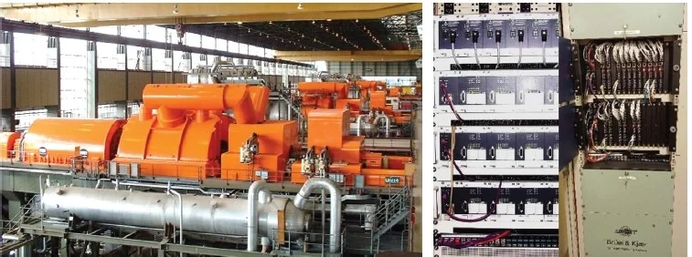
Located on the Waikato River, between Hamilton and Auckland in New Zealand, the Huntly power station was commissioned from 1982 to 1985. It features four 250 MW single reheat turbo-alternators manufactured by Parsons (UK) (see Figure 1). Unit 3, decommissioned in 2013, now serves as a source for spare parts. Notably, the turbines are installed on isolated steel support structures engineered for earthquake protection. These low-tuned structures have vertical resonant frequencies below the turbine operating speed, creating unique monitoring challenges.
Displacement sensors and accelerometers
The AVEVA PI system serves as the companywide data historian, storing process and vibration data locally at Huntly and on a mirrored corporate PI server.
Genesis Energy employs PI ProcessBook and PI Vision for data analysis, using these tools to detect anomalies that warrant further investigation.
Vibration data from monitoring systems is integrated into the distributed control system (DCS) and stored in the PI system, except for data from the SETPOINT VC-8000 system on unit 1, which is directly logged into the PI system.
This case study highlights how advanced monitoring and diagnostics systems enabled Genesis Energy to resolve a significant operational challenge efficiently.
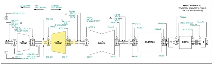
The case study presented here focuses on unit 2, though all four turbo-generator units at the power station share identical configurations. Each unit comprises a high-, intermediate-, and low-pressure steam turbine section (HP, IP, and LP) (see Figure 2). The turbine rotors are rigid, meaning they operate below the first critical speed (rotor resonance).
While the units have functioned reliably over the years, occasional issues have arisen related to the natural frequency of the flexible steel foundations near the generator turbine shaft running speed.
Monitoring strategy
Figure 2 outlines the sensor installation points and measurements for the turbo-generator units (excluding overspeed measurements).
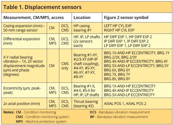
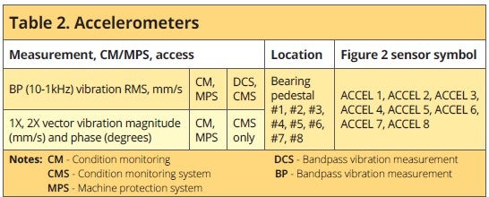
Tables 1 and 2 summarise deployment of displacement sensors and accelerometers for the steam turbine and generator components.
Due to the flexibility of the bearing pedestals caused by the steel support structure foundation, special precautions are in place for condition monitoring.
During runup (29–2850 RPM), BP (bearing pedestal) vibration alarms are set to 50 mm/s, with 1X and 2X velocity vibration alarms profiled for runup values to prevent unnecessary alerts from natural frequency resonances. If a 1X or 2X velocity vibration alert occurs during runup, it triggers a speed hold or runback within the critical speed range, while a danger alarm will trip the unit.
For speeds above 2850 RPM, bearing pedestal accelerometer-based protection is configured for BP vibration only.
Monitoring system
In 2011, the Compass Classic monitoring systems on Units 2 and 4 were upgraded to the Compass 6000/VC-6000 system (Figure 1). Unit 1 was upgraded in 2021 to the SETPOINT system, which can automatically store data in the PI system, including vibration time waveform data.
These monitoring systems offer protection and condition monitoring for the steam turbine, generator, exciter, bearing vibration, and thrust position of the main boiler feed pumps driven by a steam turbine on each unit.
Tables 1 and 2 show that some vibration data — such as BP vibration, eccentricity, differential expansion, casing expansion, and axial position — is exported to the DCS for display and trending. Units will trip if specific danger alarm thresholds are exceeded:
- Differential expansion or axial position breach.
- During run-up, 1X or 2X velocity vibration danger alarms trigger shutdowns.
- Above 2850 RPM, a BP vibration danger alarm along with another BP bearing vibration in alert status will trip the unit (voting logic in the DCS).
- Below 600 RPM, an eccentricity danger alarm will trip the unit.
Other vibration measurements are accessed via the Compass system for condition monitoring and diagnostics and include plots for velocity vibration, displacement waveforms, orbit, spectra, waterfall, Bode/polar, average shaft centreline, and amplitude or phase changes over time.
Shut down due to vibrations
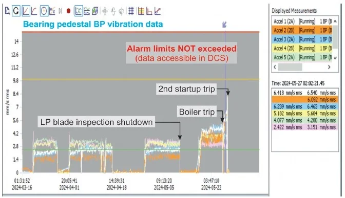
On 16 May 2024, unit 2 was returned to service following an LP turbine blade inspection (performed every 500 running hours due to prior cracking). Shortly after startup, increased vibrations at the bearing pedestals were observed, though they remained below alarm limits (Figure 4, right). On May 27, the unit tripped, but the cause was a boiler fault, not high vibrations. The boiler issue was resolved, and the unit was restarted.
During the second startup, two runup holds were bypassed in the DCS as no alarm limits were exceeded.
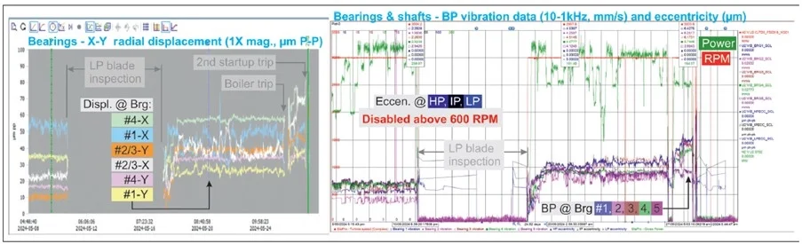
The unit synchronised and was loaded to 130 MW, but BP vibrations remained elevated (Figure 3, left, Figure 4, right). The operator contacted the Predictive Maintenance Engineer, who remotely accessed the Compass system. Analysis revealed elevated BP and 1X velocity vibrations for HP and IP turbine bearings (#1 to #4), with the 1X velocity vibration in an alarm state (not displayed on the DCS). Consequently, the Senior Operator and Predictive Maintenance Engineer decided to shut down the unit due to these findings.
Given market conditions, there was pressure to return the unit online quickly.
Diagnostics
From 27 May to 2 June, the unit was inspected to identify the cause of the high vibrations in the HP and IP turbine pedestal bearings. Checks for possible rubs in the outer gland housings and axial key wear revealed no significant issues. Meanwhile, the Predictive Maintenance Engineer analysed Compass system data, including eccentricity (disabled by the DCS above 600 RPM but monitored by Compass), bearing vector displacement (Figure 4, left), and pedestal vector velocity vibration.
Compass data showed a significant increase in BP vibration at bearings #1 to #5 before shutdown, although these values were below DCS alarm limits.
Additionally, the 1X displacement magnitude (Figure 4) for HP and IP bearings exceeded alarm limits, which could not be viewed in the DCS, similar to eccentricity above 600 RPM.
The findings pointed to a possible issue in the HP turbine affecting the IP turbine or vice versa, or a concurrent problem in both turbines.
Root cause analysis
The issue may have been caused by a bent rotor, either permanently or temporarily during operation.
Potential causes include:
- partial rub leading to uneven rotor heating;
- delay in barring the rotor while still hot after shutdown;
- Imbalance caused by erosion, corrosion, deposit buildup/detachment, or blade loss;
- bearing wear or damage;
- axial keyway wear or damage;
- a combination of the above factors.
During the initial inspection, axial key wear was ruled out, and the possibility of a permanently bent shaft was dismissed since shaft eccentricity normalised during barring. Other potential causes listed typically develop gradually, which was not observed in this case, simplifying further analysis.
Additional diagnostics were required to pinpoint the issue and restore unit 2 to operation as quickly as possible.
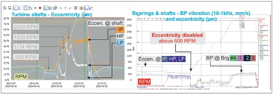
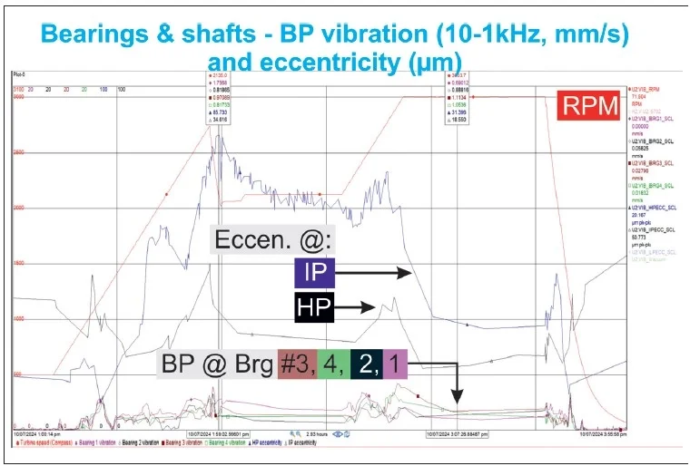
A controlled startup of unit 2 was conducted to further investigate the issue, with a portable diagnostic analyser connected to the Compass system’s buffered outputs for higher resolution data. During the test, the unit was run at manual speed holds of 500, 1174, 1500, 2000, and 3000 RPM. These speeds were selected to avoid generator critical speeds and turbine run backs. The startup was only to proceed if vibrations remained within acceptable levels. Since high vibrations were not observed, the turbine was brought to full speed.
Figure 5 summarises the results. The Compass data revealed that the IP turbine shaft eccentricity remained high throughout the runup. This confirmed the issue stemmed from the IP turbine section, not the HP section.
The eccentricity issue was initially unnoticed in the DCS trend display due to its use being primarily for assessing turbine shaft straightness at barring speeds. Eccentricity measurements are disabled above 600 RPM in the DCS to avoid dynamic effects caused by imbalance or misalignment. When enabled above this threshold, eccentricity can function as a backup for 1X displacement measurements, capturing both static and dynamic signals.
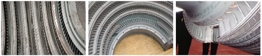
After confirming the IP turbine section as the problem source, the outer and inner casings were removed for inspection, revealing significant damage (Figure 6):
- Missing blade package in the row-one stationary blades of the top diaphragm.
- Three missing blade packages on the rotor and extensive rubbing wear across multiple stages.
- A 90° arc of missing blades in the second-row top stationary blades.
- Metal debris and severe damage to stationary blades in the casing bottom half, with blade fragments measuring no larger than 5 mm.
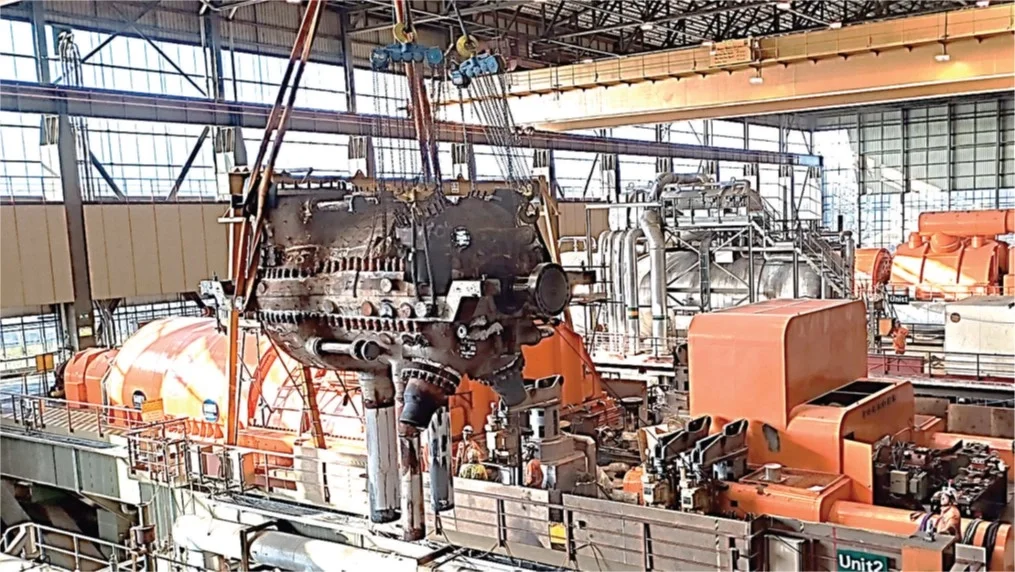
Immediate repair of the IP turbine was not feasible due to the necessity for extensive reblading of both the rotor and stationary blade diaphragms. With no spare blades available and the original manufacturer no longer in business, the only viable solution was to replace the faulty unit 2 IP turbine with unit 3’s IP section (Figure 7), which had fewer operating hours. To expedite the process, the replacement was conducted without opening the IP section for inspection or removing the unit 2 HP turbine section lid.
Repair and lessons learned
The replacement of the defective unit 2 IP turbine section with the unit 3 spare IP section was followed by immediate testing (Figure 8). The unit was returned to service within demanding time constraints and with limited repair options.
Below are listed key lessons learned and improvements implemented:
Need for improved data visibility in the control room
- Operators lacked sufficient vibration data to assess if a manual shutdown was necessary.
- Quick actions by the Operator and Predictive Maintenance Engineer prevented further damage.
- Key issues:
- 1X velocity and displacement data were not visible in the DCS.
- BP velocity data was available but not in alarm mode.
- Eccentricity data, effective in condition detection, was unavailable after 600 RPM.
- Updates:
- Eccentricity now displays continuously on DCS trends across all units.
- 1X and 2X alarms will trigger unit 2 shutdown using SETPOINT’s state monitoring once installed.
Need to enhance diagnostic processes
- IP turbine blade failures affected HP section vibration, necessitating multiple measurements for accurate diagnostics.
- Eccentricity and 1X displacement proved most reliable for detecting and localising blade damage.
- Diagnostic challenges:
- 1X velocity readings were misleading as opposing broken blade packages cancelled imbalance effects.
- Updates:
- Eccentricity monitoring is enabled at all speeds across all units for enhanced diagnostics.
Need to address monitoring system limitations
- Compass system stores time waveform and spectral data at fixed intervals, potentially missing significant events.
- Data resolution reduces over time, although eccentricity data serves as a backup to mitigate this.
- Updates:
- System uses eccentricity as a redundancy for 1X displacement data in case of resolution loss.
Monitoring enhancements required
- Blade cracking is minimally monitored due to shrouded HP and IP blades.
- Full NDT inspections, including shroud and tenon crack testing, are now standard for HP and IP rotors in prolonged operation.
- SETPOINT system upgrades for unit 2:
- event-based waveform storage replaces time-based intervals;
- data integration with the PI system;
- state-based monitoring with acceptance regions and alarms;
- full-spectrum analysis for rub diagnostics;
- programmable relay voting and detailed event logging.
The improvements listed above aim to optimise monitoring, diagnostics, and preventive measures for enhanced turbine performance and reliability.
Managing ageing equipment: the critical factor
Unit 2 has been operating smoothly since the repair, and this is expected to continue with the implemented changes.
While this case study demonstrates a quick and successful resolution, many thermal power stations with ageing turbo-generating units face similar risks, often leading to extended downtime in the absence of spare parts.
Maintenance requirements vary by plant, but one critical factor remains universal: effective machine protection, condition monitoring, and diagnostic tools are essential for managing ageing equipment.
This article first appeared in Modern Power Systems magazine.


