
All power plants require at least some water. Most require water for cooling, process makeup, and plant service uses. A substantial portion of the incoming water evaporates when used for process makeup and cooling. Dissolved solids remain behind in the liquid and concentrate. This concentrated water can no longer be used in typical plant processes. In the past, plants discharged concentrated blowdown directly to local wastewater treatment plants or to the environment. Increasingly, however, wastewater treatment plants require wastewater discharge that does not increase the level of total dissolved solids (TDS) released to the environment. It’s also getting harder to obtain permits for direct discharge of concentrated water to the environment.
What ZLD is and isn’t
Zero liquid discharge (ZLD) attempts to eliminate the problem of high TDS waste streams by removing all dissolved solids on-site and reclaiming water. Designs differ, but ZLD systems can concentrate dissolved solids until only damp solid waste remains. Solid waste is disposed of off-site and nearly all water is reclaimed and reused within the plant. While that’s the theory, reality is somewhat different. Developers, designers, and operators must understand and appreciate what ZLD is and isn’t. With that foundation, it’s possible to examine the various ZLD building blocks and designs.
Not a wastewater treatment system
A wastewater treatment system receives many different streams of varying flow with varying levels of both organic and inorganic contamination and then processes these streams to provide an acceptable effluent. However, even a well-designed ZLD system MUST operate with constant chemistry and constant flow. ZLD systems do not turn up or down well, do not turn on or turn off well, cannot tolerate deviations from the chemistry for which they were specifically designed, cannot receive any waste streams other than those for which they were specifically designed, and absolutely must be monitored continuously.
ZLD can be more accurately described as a salt removal and sequestration system. The salt arrives dissolved in the feedwater (plant blowdown), is removed by the ZLD process, and then leaves the site carrying some interstitial moisture. Most of the ZLD feedwater is reclaimed and reused. This isn’t a wastewater treatment system. Rather, it’s a chemical process with extremely stringent chemistry and flow limits. Since ZLD systems cannot tolerate variability in either flow or chemistry, most ZLD systems require the use of extremely large buffer tanks at various points in the process. Large chemical feed systems may also be required to balance chemistry. It’s ironic, but the ZLD “salt removal system” often requires thousands of pounds of salt per day, in various forms, to operate. It’s easy to spot power plants equipped with ZLD systems – one simply looks for a plethora of water and chemical storage tanks.
Not really zero
Next, ZLD isn’t zero. There’s no such thing as a true zero liquid discharge plant. If such a thing existed, water would leave the site only as a gas (water vapour or steam). Most water losses do occur through evaporation (cooling tower evaporation and demineralised water). The waste streams from these two processes represent the largest high TDS (also called “concentrated brine”) streams. ZLD designs focus on treating these streams. Other waste streams exist, but may not be suitable for reclamation in a ZLD system. Some waste streams should never be treated or fed to a ZLD system.
Sanitary wastes cannot normally be recycled onsite. Some other disposition must be arranged. Options include the installation of a package waste treatment plant or discharge to a municipal waste treatment plant. Because sanitary wastes do not contain elevated levels of dissolved solids, municipal treatment plants normally allow their discharge with no pretreatment.
Some regulatory bodies do not allow the reuse or capture of rainwater, while others allow no rainwater discharge at all. If possible or required, rainwater can be reused in the plant. After checking pH and conductivity, rainwater can be pumped to the cooling tower basin as needed. Depending on cooling tower load and evaporation rate, metering or batch operation of the rainwater pumps may be required to prevent cooling tower overflow.
Cleaning wastes of any type must be collected in a separate holding tank. Water from this tank cannot be directed to the oil/water separator or allowed to enter the plant water cycle unless tests confirm its suitability for reuse. Surfactants (detergents) in cleaning wastes may cause emulsification of the oil in the oil/water separator. Further, cleaning wastes may be hazardous, depending on additives and the metals concentration. For these reasons, cleaning wastes must be tested prior to disposal or reuse. If non-hazardous and low-volume, the cleaning waste can be directed to the cooling tower. The relatively low concentration of oil in the effluent, coupled with the high dilution factor, will usually result in oil concentration in the cooling system of less than 1 ppm. If hazardous, the water must be disposed of off-site.
Oil/water separator effluent, regardless of internal recycle, is eventually processed in the ZLD system. The primary concern is oil fouling of ZLD equipment. For this reason, an oil containment system is required. Removal options vary from mechanical filters to absorbents. An oil containment system can be installed on the oil/water separator effluent line or on the ZLD feed inlet line. The goal remains the same in either case – no oil can be allowed to foul the ZLD system.
Many other potential waste streams exist. Each stream should be evaluated using the following criteria:
• If the stream is low-concentration plant makeup water and contains no oil, route the stream to the cooling tower.
• If the stream is low-concentration plant makeup water and may contain oil, route the stream to the oil/water separator.
• If the stream contains concentrated plant makeup water with no oil, route the stream to the zero liquid discharge system or the cooling tower. Neutralisation tank waste streams, if present, should be routed to the zero liquid discharge system.
• If the stream contains concentrated plant makeup water and may contain oil, route the stream to the oil/water separator.
• Sequester and haul the water off-site if the stream is hazardous, contains significant oil or organics, or is of unknown composition.
A water reclamation system
Plants experience two basic types of water loss – recoverable and unrecoverable. Evaporation results in unrecoverable loss to the atmosphere (although there has been some experimentation with evaporative loss recovery). Examples include cooling tower evaporation and drift, demineralised water used for inlet air-cooling, steam used for power augmentation, or steam losses. Once this water enters the atmosphere it’s gone and it won’t come back.
Anything other than unrecoverable loss is, by definition, recoverable. Although expensive, any liquid stream can be recovered and reused. Examples include cooling tower blowdown, steam cycle blowdown, pretreatment system wastewater, plant service water, and various leaks and drains.
Permitting agencies often require or strongly encourage the use of ZLD systems because they believe ZLD systems conserve water. While that is true, the numbers aren’t as large as one might think. Consider Figures 1 and 2. Figure 1 shows water use for a traditional plant that discharges cooling tower blowdown and demineralization waste off-site. The plant uses about 590 m3/h (2600 gpm) of fresh water and discharges about 124 m3/h (544 gpm) of wastewater. The plant wastes approximately 21% of the fresh water it receives.
Figure 2 shows that a ZLD system can recover nearly all of that wasted water, but the majority of this plant’s water loss is unrecoverable. Even though the ZLD system lowers the percentage of wasted water from 21% to about 0.1%, the system saves only 20% of the water that the site requires. If water conservation is the goal, much more efficient methods exist. Air-cooled condensers, for example, use a fraction of the water that a traditional plant requires. Unfortunately, air-cooled systems lower plant efficiency, cost more, and increase parasitic load. Once-through cooling provides another option, but is dependent on location.
So developers are left with one poor option. Even well designed ZLD systems are expensive, hard to operate, exhibit poor reliability, and require high parasitic load. To quote Sir Winston Churchill, “It has been said that democracy is the worst form of government except all the others that have been tried.” Similar logic applies to ZLD systems. They’re extremely problematic, but the alternatives are often worse.
ZLD building blocks
Zero liquid discharge consists of five basic processes. They are: initial concentration; sparingly-soluble mineral removal; membrane concentration; thermal concentration; and liquid/solid separation. These processes may overlap and, in some cases, a process may be eliminated entirely. However, an understanding of these five basic processes is essential to an understanding of the options available for zero liquid discharge.
In general, the cost of concentration is proportional to the level of dissolved solids of the concentrated material. Evaporation in the cooling tower is essentially free, for example, while evaporation to dryness may cost as much at $US40 for every thousand gallons of water evaporated. The zero liquid discharge system design attempts to move concentration from the “back end” to the “front end” of the plant since front-end concentration is less expensive. The amount of water to be concentrated lowers with each step in the process.
Initial concentration
Initial concentration occurs in the cooling tower. The level of concentration obtainable in the cooling tower depends on the incoming makeup water quality and its propensity to form scale. Typically, makeup water can be concentrated 3-10 times in the cooling tower, raising TDS to 2500-8000 ppm. Water high in scale-forming dissolved solids (like calcium or silica) can be concentrated only a few times prior to being removed from the system via blowdown. Water low in scale-forming dissolved solids may be concentrated ten or more times prior to removal through blowdown.
Concentration in the cooling tower represents the most efficient process. Therefore, cooling water cycles of concentration should be as high as possible.
Sparingly-soluble mineral removal
Concentration in the cooling tower is limited by the solubility of scale-forming minerals, usually calcium or silica. Scale-forming minerals must be reduced, removed, or stabilised to increase concentration above that obtainable in the cooling tower. Failure to remove scale-forming minerals will result in scale formation in membrane concentration processes.
Sparingly-soluble mineral removal may not be required if makeup water purity allows the cooling tower to operate at greater than six cycles of concentration. Although economic analysis is necessary, relatively “good” makeup water quality often allows higher concentration in the cooling tower and eliminates the need for membrane concentration.
Mineral removal requires the use of either a reactor/clarifier or ion exchange. A reactor/clarifier uses precipitating chemistry to convert sparingly-soluble dissolved ions into solids. These solids must then be removed, compressed, and disposed of as solid waste through a sludge handling system. Ion exchange is usually economic only if cooling tower cycles of concentration are limited by calcium. In this case, either sodium zeolite or weak acid cation softening reduces calcium concentration. Total dissolved solids in the process effluent may be unchanged, higher, or lower depending on the process used. In any case, the goal is to either replace less soluble species (calcium, magnesium, and silica) with more soluble species (sodium or hydrogen) or to remove the dissolved solid completely.
Mineral removal may be accomplished after initial concentration in the cooling tower (“side-stream” or “cooling tower blowdown” softening) or before initial concentration in the cooling tower (“makeup” or “front-end” softening).
Membrane concentration
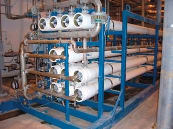
Membrane concentration uses reverse osmosis to concentrate TDS as much as possible prior to thermal concentration. Sparingly-soluble minerals must be removed or stabilised first to prevent membrane scaling, but the removal process isn’t perfect. These remaining minerals concentrate in the reverse osmosis reject. Either the concentration of scale-forming minerals or osmotic pressure limits RO recovery. Reverse osmosis permeate usually returns to the cooling tower for reuse. It can also be used as demineralisation system makeup. Feedwater into the membrane process usually falls in the 2500-8000 ppm range. Membrane concentration raises waste stream total dissolved solids to the 20 000- 60 000 ppm TDS range and minimises the volume of water that must be treated in more expensive thermal equipment.
Many of these membrane processes incorporate the use of a decarbonator. Since decarbonators typically vent to atmosphere, this source must be considered in total plant particulate emissions. The impact on total plant particulate emissions will generally be negligible, but must be verified.
Thermal concentration
Thermal concentration uses applied heat to boil concentrated waste stream. Heat application methods vary. Direct steam heating, though inefficient, may be used. Thermo-compressors and vapour compressors are more common. Designs vary, but typical thermal concentration equipment consists of a brine concentrator (also called an evaporator), a crystalliser, or both. These units increase the boiling point of the feed stream, form concentrated liquor, and create high-purity distillate. Mineral precipitation begins. Calcium sulphate forms at lower temperatures (typically found in a brine concentrator) while sodium chloride forms at higher temperatures (typically in a crystalliser). If the feed stream volume is relatively small both calcium sulphate and sodium chloride precipitation can be achieved in a crystalliser. The distillate formed is usually of very high purity and is often used as demineralisation system makeup.
These two mineral compounds contain the majority of dissolved minerals that initially entered the plant with the raw water. Other minerals like magnesium, potassium, and silica generally co-precipitate with either calcium sulphate or sodium chloride.
Brine concentrators can typically raise total solids to 20-25%. Suspended solids (precipitated minerals) concentration usually falls in the 3-10% range while dissolved solids typically falls in the 12-17% range. Brine concentrator effluent is too low in suspended solids to allow direct liquid/solid separation. Precipitation of sodium chloride, usually in a crystallizer or solar evaporation pond, is required.
Crystallisers are less thermally efficient, but increase total solids to the 50-60% range. Crystalliser slurry can be sent to direct liquid/solid separation.
Liquid/solid separation
Liquid/solid separation removes moisture from the concentrated slurry and creates a damp solid suitable for disposal off-site. It requires the use of solar evaporation ponds, filter presses, centrifuges, or dryers. Centrifuges or belt presses are most often used to separate the concentrated liquid from the final effluent sludge. Water from this portion of the process returns to the crystalliser. Solids are sent to portable storage bins and disposed of off-site.
Solar evaporation ponds offer an excellent alternative if permitting and space allow, but do require periodic cleaning. The simplest (and most reliable) ZLD design sends cooling tower blowdown directly to a brine concentrator and brine concentrator effluent directly to a solar evaporation pond. In addition, most permitting authorities require posting a bond to cover the cost of evaporation pond removal and site remediation at the end of the plant’s expected life.
Final thoughts
Figure 3 shows a decision tree providing a visual guide incorporating the concepts explored above. It’s important to remember that each situation requires detailed financial analysis and many other options and combinations exist. The decision tree is best used as a starting point, but should not be used to as the final determinant in a ZLD design.
Wastewater discharge often presents the largest challenge in power plant water treatment system design. Makeup water is usually available, but many locations require wastewater discharge that does not increase the level of total dissolved solids in treated effluent. Power plants generally concentrate makeup water total dissolved solids (TDS) between 4 and 10 times. Discharge volume is usually 10%-25% of influent water flow rate. Zero liquid discharge systems lower that value to less than 1%. This small remaining volume can be evaporated to dryness in solar evaporation ponds or through applied heat.
Since ZLD design depends on influent water quality, no standard design is possible. Broad choices exist, but the plethora of design options always requires detailed analysis. A few truisms do exist, however:
• Most plants hate the ZLD systems they have, regardless of manufacturer.
• Zero liquid discharge is a last resort. Discharge to others if possible. While capital cost may appear relatively low, most ZLD systems cost $US25-$US35 million dollars in net present value when manpower, maintenance, and consumables are factored into the equation. Use that money during development to avoid ZLD.
• Consider deep-well injection. It’s easier and less expensive than ZLD.
• Minimise the use of intermediate processes requiring chemical precipitation and avoid completely, if possible. Minimise processes that require chemical feed.
• Move concentration as far back in the system as possible. Concentration in the cooling tower costs nothing and should be maximised.
• Reuse un-concentrated and low-concentration TDS waste streams in the cooling tower if water quality permits.
• Use the decision tree as a guideline only. Site-specific situations require site-specific designs.
• Consult experts and join users’ groups. Martin Vanbee, a historian, said “Learn from the mistakes of others. You can’t live long enough to make them all yourself.” That’s particularly relevant to ZLD systems.


