
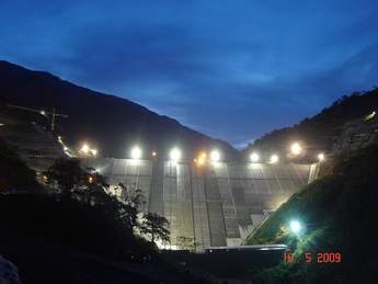
Kárahnjúkar dam, Iceland
Approved by the Icelandic Parliament in 2002, construction of the Kárahnjúkar hydroelectric project started in 2003 with completion in 2008. The 690MW project, which has an annual generating capacity estimated at 4.6TWh/yr, was built to provide power for a new aluminium facility built by Alcoa, US, on the east coast of Iceland. Landsvirkjun, the National Power Company, owns and operates the plant and has a 40-year power purchase agreement with Alcoa. Financing was secured by Landsvirkjun using mostly European banks.
Economic development of the project was based on a head of 600m. The low lying Fljótsdalur valley cuts the highland plateau north of Vatnajökull and creates such a high head for power production.
The Jökulsá á Dal river is dammed at the Kárahnjúkar hills with three dams. The largest one, Kárahnjúkar dam, crosses the southern (upper) end of the Hafrahvammar canyon and is about 700m long and 198m high. This is among the highest CFRDs in the world and is the highest of its kind in Europe. During construction the river was diverted through two diversion tunnels under the western bank of the dam. Two smaller rockfill dams with earthern core, 68m and 29m high respectively, were built on each side of the Kárahnjúkar dam.
The Kárahnjúkar CFRD has a rockfill volume of 9Mm3 and was built by Impregilo of Italy. The rockfill was produced from a quarry inside the reservoir just upstream from the dam and was partly transported into the dam after crushing and screening by conveyor belts. The concrete face slab was cast in 15m wide bays by slip forming.
The dam crosses a deep canyon with vertical cliffs. It was designed to cross the canyon on the upstream side, with a massive 50m high concrete toe wall in three separate monoliths, instead of a more conventional concrete foundation plinth at the toe of the face slab. The toe wall is designed to withstand fault movements using elastic joint sealing measures and the dam as a whole to withstand a heavy earthquake.
The grout curtain below the dam extends to a bedrock depth of 100m. A gallery is provided at the toe of the dam for later inspection and eventual further cement grouting.
To keep the project on schedule the dam construction, including concrete works, had to continue through the winter periods, casting concrete under cover and using heating measures. Excavation at the dam foundation started mid 2003, and the diversion tunnel gates were shut to start lake impounding in September 2006. The reservoir reached the full level of 625m asl late in the summer of 2007. Seepage under the dam at full pressure is approx 200l/sec, which is well below what was expected at this site. Settlements of the fill are also well within expectations. This is important as the dam is one of the highest of this kind in the world and the concrete membrane is sensitive to excessive settlements. Monitoring of movements show that the membrane is performing very well and movements of the joints are minimal.
Two saddle dams on each side of the Kárahnjúkar dam, one of which is 68m high, and three further dams on the eastern river are all rockfill dams with a central core of moraine. These dams with a combined volume of 6Mm3 were built by local contractors Suðurverk, Arnarfell and Istak.

Karahnjukar Dam. Photo by Emil Thor Sigurdsson
Shuibuya dam, China
At 233m high, Shuibuya dam is currently the tallest CFRD in the world. Completed in 2008, the dam is part of the 1840MW Shuibuya hydro power project located in Badong County in the middle reach of Qingjiang river, a tributary of the Yangtze river. Total reservoir volume for the project is 15.64Mm3.
State of the art CFRD techniques were applied to the dam construction, including: optimized rockfill construction steps, dynamic compaction of riverbed foundation, introduction of a new type of waterstop, permanent horizontal joints, GPS recorded compaction tracks and advanced instrumentation.
The successful completion of Shuibuya dam not only broke the theory among dam engineers that CFRDs could only be built under 200m, but it also made technical breakthroughs with regards to construction of these types of dams in a karst region.
In Shuibuya, the compaction was also very strict. Fibres were incorporated into the concrete in order to reduce the frequency of cracks on the slab, which often occurred during construction.

Shuibuya Dam. Photo courtesy of Bayardo Materon
La Yesca dam, Mexico
Located on the Santiago river, 62km upstream of the El Cajon project (discussed later), on the border of Jalisco and Nayarit, the 220m high La Yesca CFRD is being developed by Mexico’s Comision Federal de Electricidad as part of a 750MW hydroelectric project.
The dam – which will have a crest length of 628.77m – is being built by a consortium led by contractor Ingenieros Civiles Asociados (ICA) and comprising Promotora e Inversora Adisa, La Peninsula Compania Constructora and Constructora de Proyectos Hidroelectricos.
The dam consists of a rock curtain with a concrete surface, with the body formed of graduated materials in 15m high panels of variable thickness. The concrete surface rests over a pedestal that also works as a platform to allow for injections of consolidation and impermeable screen that, alongside a gallery system excavated on both sides of the rock curtain, will form the stem plane.
The concrete surface will have a system of seals and cupper joints and PVC which will be placed on all the joints of the concrete surface and on the perimeter joint of the base-concrete surface to help guarantee minimum filtrations. To measure these filtrations, a filtering gallery will be placed on the bottom of the curtain on the downstream zone.
The project is scheduled for completion in June 2012.

The main cofferdam at the La Yesca project. Courtesy of Bayardo Materon
Merowe dam, Sudan
The Merowe Dam project is situated on the Nile River, close to the 4th Cataract where the river divides into multiple smaller branches with large islands in between, near Merowe city, which is 350km to the north of Khartoum. The dam is located at longitude 32 E, and latitude 19 N.
The Merowe Dam was designed to serve several purposes, namely: the generation of electricity from its 1250MW hydro power station; the development of centralized agricultural irrigation schemes (about 300000 ha); and, the protection of the Northern State against devastating high floods from the Nile.
Furthermore, the dam will act as a sediment trap, reducing sedimentation at the Aswan High Dam further downstream in Egypt.
Because of the topographical conditions at the dam site, the project features a dam with a total length of about 9.3km, which consists of the major dam structures as shown in the table below.
The powerhouse, which will accommodate the project’s ten generating units, was arranged at the downstream toe of the power intake dam. Irrigation outlet structures are provided on the right and left banks to release water for future irrigation developments.
The Earth Core Rockfill Dam (ECRD)
The main dam of the Merowe project is a classic earth core rockfill dam (ECRD) with a central earth core (zone 1), fine and coarse filters (zones 2 and 3) and upstream and downstream rockfill shoulders (zone 4).
For the construction of the cofferdams, random rockfill (zone: 7) was used. The ECRD is founded on alluvial sediment, which are up to 30m thick. To avoid seepage, a 1m thick plastic concrete cut-off wall is provided, which penetrates about 4m into the bedrock. On top of the cut-off wall a cushion of highly plastic material is provided, to avoid stress concentrations in the wall and cracking of the core.
To achieve the required factors of safety, the upstream and downstream shoulders were sloped at 1V:2H and 1V:1.8H, respectively. With a total length of 883 m- and a height of 64 m, the ECRD has a total volume of 8.25 x 10m3 . The upstream and downstream cofferdams were designed to protect the construction pit against the 100 year flood.
Some key dates on the project construction are:
• On 12th December 2003, the river’s course was diverted to the right side, in preparation for construction works at the riverbed. Since that day the Nile course has been made to pass on the left side of Mirowe Island.
• A temporary sand-made wall was built following 48 hours of continuous work to block the Nile path completely. The temporary assisting barrier was then constructed, and the water was pumped out from the area that falls between the two blockades. The area was dried out to allow construction work to begin.
• During the period 5-8 August 2004, a delegation from the Hydroproject Institute reviewed the excavations for the dam’s foundation. The High Technical Consultancy Committee was also briefed on the preparations to start concreting works.
• On Tuesday 9th November 2004, the Contractor started to pour the first concrete mix in the dam’s body.
The concrete faced rockfill dams
CFRDs were selected on both the left and right banks for economic reasons. Because of the prevailing topographical conditions, the CFRDs extend some 1590m to the left and 4315m to the right. The zoning of both CFRDs is conventional, consisting of a transition zone, fine, coarse, and random rockfill. To facilitate the compaction of the transition zone, and the construction of the concrete face slabs, extruded concrete curbs were placed throughout, which proved to be very beneficial. The upstream and downstream slopes are inched at 1V:1.3H and lV:I.5H, respectively. The total volume of both CFRDs is 5.3 x 10m3.
The concrete plinth was founded mostly on moderately weathered to sound rock, which required excavations to a depth of between 3-5m. Seepage control was achieved by a single row grout curtain with an average depth of about 20m. Because of the lengths of the plinths, slip forms were used throughout.
Of particular interest is the interface between the ECRD and the CFRD, which required the design and construction of a 48m high concrete interface structure.
Towards the ECRD, this structure is sloped to provide a watertight pressure joint between the core and the concrete wall. Towards the CFRD, the slope of the structure becomes gentler (1V:0.4H) to minimize differential settlements along the parametric joint.
The power intake dam
The power intake dam is a steel-reinforced concrete structure 300 m long and 67 m high, which accommodates ten power intakes. Each of these intakes is designed for a rated discharge of 300m3/sec, and is equipped with a trash rack, stop logs and a submerged roller gate with a 8.5m clear width and 10.5m height. Downstream of the roller gate, a transition zone conveys the water from the rectangular gate opening to the circular cross-section of the penstocks. The penstocks have inner diameters of 8.5m, with a steel thickness of 18 to 32mm, depending on the head. They are fully embedded in steel reinforced concrete. The so-called GIS Building, which accommodates the 500kV-GIS switchgear, is placed on the downstream slope of the power intake dam.
Originally, the power intakes were designed for a minimum reservoir water level of el. 290, which was lowered at a later design stage to 285m, to allow for operation during extremely dry years. This design adjustment called for extensive hydraulic model test at a scale of 1:40, to study the required submergency to avoid vortex formation and air entrainment.
From the structural point of view, the power intake dam could not be dimensioned as a conventional concrete gravity dam. The 11.5m-wide and 13m-deep blackouts for the penstocks significantly changed the structural behaviour of the concrete dam and required the introduction of steel-reinforced shear walls between the penstocks to transmit the loads into the rock foundation safely.
Porce III, Colombia
Due for completion in 2010, the 844MW Porce III hydroelectric project involves impounding the Porce River through construction of a 155m high CFRD dam with a crest length of 426m. The dam will have a chute located in the left abutment with a discharge capacity of 10,850m³/sec, controlled by four radial gates and a flip bucket for energy dissipation.
The general layout of the works is complemented by the diversion tunnel and low level discharge, the power generation installations which consist of a vertical shaft and headrace tunnels, an underground powerhouse distributed in two caverns: generators and transformers, cable and ventilation galleries, a gate gallery and tailrace tunnel that restores the water back into the river through an energy-dissipation channel.
Ingetec, in joint venture with Klohn Crippen Co. Ltd, undertook the detailed designs of the Porce III Dam for Empresas Publicas de Medellin – E.S.P. (Medellin Public Utilities Company). The main characteristics of the CFRD are as follows:
• Height: 155m
• Crest length: 426m
• Crest width: 8m
• Total reservoir volume: 170hm³
• Catchment area: 3698km²
• Total foundation excavation volume: 125,000 m³
• Total plinth excavation volume: 425,000 m³
• Total fill volume: 4.15Mm³.
Just after completion of the detailed designs for the Porce III dam, the news arrived about the occurrence of concrete cracking at high CFRDs. However, such undesirable behaviour was not expected at Porce III as its characteristics are similar to other dams that have behaved adequately. Nevertheless, design revisions and minor adjustments were still introduced as additional measures to prevent any untoward behaviour.
The design of Porce III dam has paid special attention to reducing the compressibility of the upstream shoulder and including vertical joints with a deformable infill in the central portion of the concrete face.
The need to ensure the highest deformation modulus possible led to the adoption of a thinner layer of concrete and a greater number of passes using a heavier compactor.
The best rocky material available was also placed, with a high uniformity grading coefficient being achieved by using an adequate quantity of water during placement and compaction.
In its first stage of construction, detailed field investigations were performed on the rockfill acquired from the different excavations. Because of the nature of the rock, the design has had to verify the deformation modulus of the rockfill which is required for adequate support of the concrete face.
To dissipate the high stress levels in the concrete face, five central vertical compressible joints were also incorporated, together with a deformable infill between joints, with a modulus of about 10MPa.
A 3D finite element model was developed to evaluate the stresses and strains of the concrete face during different stages of dam operation. Based on the modulus and deformations obtained from laboratory and field tests performed on the rockfill material, it was established that the maximum deformation of the concrete face due to the reservoir impounding is in the order of 30m and takes place in h/H total between 0.43 and 0.45.
Upon completion of the first reservoir fill, the maximum horizontal displacement of the dam crest is calculated to be 22cm, and the maximum vertical displacement is 30cm. The unit deformations of the rockfill increase up to 0.2% and 2%, for the horizontal and vertical components, respectively. Under these deformations, the analytical modulus indicates that the behaviour of the concrete slab should be satisfactory.
As the construction of the dam progresses, further refinement of the analyses will be performed.

View of the slab construction at Porce III. Photograph courtesy of Bayardo Materon
Barra Grande, Brazil
The Barra Grande dam is 187m high and 665m long. The dam is situated on the Pelotas river, 43km from its confluence with the Rio Canoas in Brazil. It has a face slab thickness of 0.3+0.002H> 0.005H, with an upstream slope of 1.3 and downstream slope of 1.4. The structure is built with basalt rockfill and has a rockfill volume of 1Mm3. Reservoir capacity stands at 5Mm3. The hydroelectric project has 3x236MW Francis units and is operated by Energética Barra Grande SA.
Construction got underway in 2001 and was completed in 2005. However, in September 2005 extensive rupturing of the concrete face under compression occurred. Reservoir leakage was at a constant 150 l/sec and reached 1280 l/sec by the end of January 2006.
Extruded curb elements were used as the finishing surface for the upstream face of Barra Grande dam. These were first devised for the construction of Itá dam in Brazil in 1999, and are considered to be a practical way to:
• Define the upstream face and confine the upstream transition for compaction.
• Provide a stable surface for protection against erosion from rainfall runoff.
• Set up a firm surface for construction of the concrete face.
The use of curb elements has become a way of life in practically all CFRDs built since Itá. The possibility that these could contribute to compression incidents has been raised but the arguments have not been convincing to the point of inducing the abandonment of the practice. Bond-breaker products between the curb surface and the concrete slab have been suggested to possibly reduce the shearing forces transmitted at the interface. Thus, at Barra Grande plastic sheets were placed over the curb elements to produce a bond-breaker effect.
In June 2007 soil material was dropped over the crest in order to reduce leakage. Consequently leakage dropped to 800l/sec.
Even after the reported incident at Barra Grande, the CFRD structure remained inherently safe. The operation of the dam was not affected during the episode and there was no concern at any time about the safety of the dam. Such confidence in the structure explains why CFRDs have become popular and are still built worldwide.

Cross section of the Barra Grande Dam
Mohale dam, Lesotho
The Mohale dam in Lesotho forms part of Phase 1B of the Lesotho Highlands Water Project. The 145m high CFRD, with a crest length of 540m and an embankment volume of 7Mm3, collects flows from the Senqunyane river for diversion to the main Katse reservoir (formed by the 185m high concrete arch Katse dam) via a 32km tunnel. From there, the water is transferred by an 82km long tunnel system, via the 72MW Muela underground power station, to the headwaters of the Vaal river in the Republic of South Africa to provide additional water to Johannesburg.
Mohale dam was built from basalt rock and construction was completed in 2002. The main embankment dam has an upstream concrete face slab, plinth and parapet wall. A 50m wide ogee weir spillway, including a chute and flipbucket, are located on the left abutment. There are also two diversion tunnels, an upstream cofferdam (27m high with a bypass canal) and a 7m high downstream cofferdam.

Mohale dam, Lesotho
Campos Novos, Brazil
Campos Novos dam is located on the Canoas river in the Brazilian state of Santa Catarina. Construction of the 202m high, 12Mm3 dam began in October 2001 and was completed in February 2005. The rockfill embankment, originated from basalt rock, was divided into zones so that the upstream third and the central area of the dam material – denominated as 3B and 3D – were compacted in layers 1m thick, wetted at the rate of 200 l/m³. The voids factor of these zones was equal to 0.22 on average and the compacted unit weight is 2.14 tonnes/m³.
The downstream third, consisting of materials of the 3C/3D type, was compacted in layers of 1.6m without wetting; the average unit weight of this zone being 2.02 tonnes/m³. The transitions under the slab – materials 2B and 3A – were compacted in layers of 0.5m reaching void factors of about 0.20.
The rockfill embankment was implemented in three stages and the concreting of the slabs of the face in two stages. The rockfill embankment was first raised upstream and the slabs concreted up to el.568m, which corresponded to approximately 52% of the final height of the dam and flood recurrence period of 1:500 years.
The downstream rockfill embankment was then raised to el. 570m and later to el. 660m. Slab concreting was carried on after the completion of the rockfill embankment. The average production of compacted rockfill was 700,000m³/month, while the 16m wide slabs were implemented at an average speed of 2.9m/hr.
El Cajon dam, Mexico
El Cajon hydro power dam is on the Santiago river in the Mexican state of Nayarit. It is located 80km east of Tepic City, 60km upstream of the existing Aguamilpa project. Construction began in 2003 and was completed in June 2007, at a cost of US$800M.
The 640m long dam is 178m high. Its reservoir capacity of 5x10⁹m3 is used to help regulate basin runoff and benefit the Aguamilpa region. Operated by the state-owned company Comision Federal de Electricidad, the 750MW scheme is capable of supplying 2% of Mexico’s electricity demands.
The rockfill used in the dam mainly came from an Ignimbrite rock of riodacitic composition, obtained from the right riverbank. The rocky mass of the site where the works were located – particularly on the left riverbank – presented a number of geological faults and superficial thickness of decompressed rock with values RQD from 0-50% up to 50m deep. Excavations and treatments to the rock were needed in order to obtain an adequate foundation for the plinth.
An extensive campaign of field studies and laboratory tests was carried out to determine the geotechnical properties of the rockfill that could be used in the dam. Diverse stress-deformation analysis of the dam using the finite element method was also carried out. The seismicity of the region is low, so seismic analysis was not a major consideration during the dam design.
The diversion structures consist of two tunnels (734 and 811m long) excavated in rock, located on the left bank. The tunnels are designed to discharge 6481m3/sec, with two main cofferdams. The upstream cofferdam is 48m high, with the downstream cofferdam standing at 15m high.
The spillway, also located on the right bank, is of an open channel design, controlled by six gates with a total capacity to discharge 14,864m3/sec when conveying the design flood with a peak flow of 15,915m3/sec.
The project features an open power intake channel, two penstocks, an underground power house with 2x375MW Francis turbines (maximum capacity of 416.7MW each), a surge chamber, tailrace tunnel and outside switchyard, all located on the right bank.

El Cajon dam in Mexico
Itapebi, Brazil
Construction of Brazil’s 120m high Itapebi dam was completed in 2003. The 3900×103m3 rockfill dam used compacted basalt and gneiss respectively. It was built on sand deposits and innovative construction methods were required. The plinth was built by slip-forming using the internal slab technique for reducing excavation.
Itapebi was the first dam where construction of the face slab was simultaneously done with upstream rockfill placement. The upstream slope was 1.25H: 1V. A coordinated operation was carried out to build the slab and the upstream fill.
The face slab at Itapebi was divided into three phases. The construction method adopted required building an external platform, which was used for providing services such as water, air and energy and logistical access for personnel and concrete.
This temporary platform, supported by anchorages, was structurally calculated to provide reaction for climbing the slip form using hydraulic jacks and cables. Phase l was built at the same time as the upstream rockfill was placed, permitting the lower fill over the slab, suspending pumping and improving the construction schedule.
Leakage was relatively high and augmented by cracking of the slab, due to further saturation of the fill increasing creep and tensile strains at the face slab. Throwing fines into the reservoir effectively treated the leakage. Reduction of leakage from 1700l/sec to 50l/sec was obtained.


