The Opuha Dam was the result of a community led initiative to address the problems experienced from persistent and often severe water shortages in the South Canterbury region of New Zealand. The economic development of the predominantly agricultural region was being hindered by unreliable water availability and the community was very concerned that the recreational, ecological, cultural and utility values of the main river, the Opihi, were being severely compromised when the river ran low or even dry at times. The search for a solution initially concentrated on sourcing alpine water from outside the catchment but eventually an in-region storage project was agreed on.
After nearly 16 years since the first community meeting was held to discuss the region’s water shortage problem, the construction of Opuha Dam was completed in November 1998.
Project description
The Opuha Dam is situated at the confluence of the North and South Opuha rivers, located 17km northeast of Fairlie in South Canterbury.
The site comprises four main components – the embankment dam, the power station at the base of the dam, the regulating pond and the downstream weir.
Water is released continuously from the scheme to maintain viable flows in the downstream rivers and provide for irrigation abstraction from the river. Priority is given to environmental releases and community water supply, with irrigation use ranked third. Under normal operation, all water released from the dam is passed through the hydropower station which discharges into the downstream regulating pond. A radial gate at the downstream weir regulates the release to the river.
The Opuha Dam and facilities are owned by irrigating farmers and the overall Opuha scheme includes downstream irrigation distribution infrastructure providing access for irrigation of 16,000 hectares.
The power station and river regulation gate are operated remotely from Tauranga in the North Island under a contract with Trustpower.
Opuha Dam
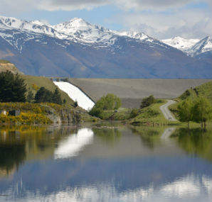
Opuha Dam is a 50m high embankment dam with a crest length of around 300m. The dam is situated at the confluence of the North and South Opuha rivers and impounds the 700ha Lake Opuha, with a storage volume of approximately 72Mm3. It comprises a zoned earth and rockfill dam (clay core rockfill, CCRD), with a downstream chimney filter. The dam is comprised of approximately 800,000m3 of fill and is founded on rock. Construction materials were sourced from the dam vicinity. It has a ‘high’ Potential Impact Classification (PIC) in accordance with the NZSOLD Dam Safety Guidelines.
The primary spillway is located on the right abutment and comprises a fixed crest at RL391.2m, which can be raised to RL392.2m via installed mechanical gates (three Obermeyer water control gates). The primary spillway is 35m in width, with an effective crest width of 32m, and has a maximum discharge capacity of approximately 300m3/sec at RL 394.25m (equivalent to an estimated 1:200 annual exceedance probability (AEP) flood). The spillway is a concrete lined, stepped design, with a concrete training wall on the LHS and a shotcreted rock slope on the RHS. The primary spillway discharges via a flip bucket into an unlined stilling basin. A single lane bridge, supported on concrete piers, provides access over the spillway.
An auxiliary spillway is located on the left abutment of the dam and includes a two-level fuse plug (zoned embankments, approximately 2000m3), intended to commence fusing at a 1:200 AEP flood event. The crest levels of the fuse plugs are set at RL394.2m and RL394.5 m, with the higher fuse plug set to fuse at a 1:3,000 AEP flood event. The two fuse plugs are 25m wide. The auxiliary spillway has a total discharge capacity of approximately 900 m3/sec, which combined with the primary spillway, provides the ability to pass the probable maximum flood (PMF, approximately 1200 m3/sec).
The dam was overtopped during construction in February 1997 when embankment construction had reached approximately RL373m. The resulting breach removed approximately one third of the dam adjacent to the left abutment and resulted in damage to the low level conduit RCC surround and piezometer installations. The subsequent repair work delayed the construction programme by approximately 12 months.
Following a safety review of the dam (SMEC 2004), remedial works were undertaken to the main dam. These included:
The placement of a two-stage filter upstream of the existing chimney drain on both abutments to reduce the risk of cracking and internal erosion.
The provision of a rock overlay on the dam toe to increase the ability of the dam to pass elevated seepage flows that could possibly result from erosion and an increase in permeability within the seepage control zone.
The construction of a concrete cut-off wall and drainage monitoring facilities at the dam toe.
Power Station
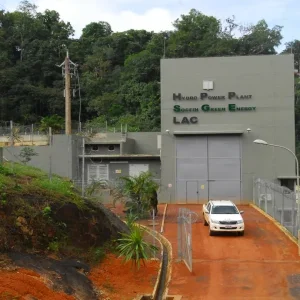
The power station comprises a single, conventional horizontal Francis hydro turbine directly driving a synchronous generator with a continuous capacity of 7MW, based on a flow of 16.3m3/sec. The generation plant is located in a deep silo type annular power station structure at the toe of the dam.
Water is drawn from the bottom of the lake via a 200m long horizontal penstock with a butterfly isolation valve immediately upstream of the turbine. The vertical inlet to the penstock is protected by a removable inlet screen ‘cage’. A steel tower stands alongside the inlet and a gantry crane on top of the inlet tower structure is used to remove the inlet screen and place an inlet ‘plug’ in the inlet to isolate the penstock for inspection and maintenance. Divers are required on site for his isolation operation.
In the event the power station is out of service, the water can still be released through the penstock via an energy-dissipating cone valve which bypasses the power station.
Regulating Pond and Downstream Weir
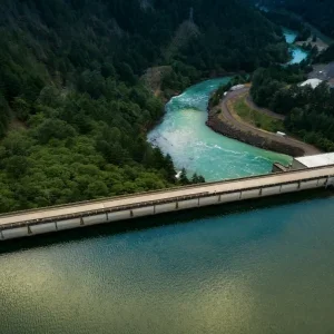
The regulating pond extends 1.5km downstream of the power station and is formed predominantly from the original riverbed but terminates with a 480m long enclosure embankment that creates a broad pond. Within the enclosure embankment are a radial gate structure; a gated, concrete overflow spillway; and a fusible overflow section.
The function of the regulating pond is to enable the power station to be operated at optimum efficiency and at periods to meet high electricity market prices while maintaining a steady release into the river. Typically, the power station operates at full load (7MW, 16m3/sec) twice a day which sees the regulating pond level rise and fall as a steady flow (2-10m3/sec depending on downstream water demand) is released into the river.
The regulating pond has an approximate surface area of 10,000m2 and a maximum stored depth of water of 7m when full. It has a total designed storage capacity of approximately 300,000m3, derived largely by excavation into ‘river bed gravels’.
Fuse Plug Embankment
The fuse plug (overflow) embankment section extends for 70m from the left abutment of the downstream weir to the concrete spillway. It has a maximum height of 7m. It comprises a homogeneous embankment with an upstream low-permeability liner, formed with a 4m crest width, 2.5H:1V internal slopes and 2.25H:1V external slopes. It is founded primarily on soil (gravel).
The fuse plug has fused twice previously, in 2002 and 2009, and reinstatement has occurred in general accordance with the original design. The capital costs of reinstating the fuse plug in 2009 was approximately NZD$250,000.
Enclosure Embankment
At 350 m in length, the enclosure embankment (non-overflow) extends from the right abutment of the ODDW to the gate structure. It has a maximum height of 7 m. It comprises a homogeneous embankment, formed with a 4 m crest width, 2.5H:1V internal slopes and 2.25H:1V external slopes. It is founded on soil (gravel).
Gate Structure
The gate structure is located on the right hand side of the concrete spillway and is founded on rock. It includes a 3m wide x 1.5m high radial gate and associated controls.
Concrete Spillway
The concrete spillway (ogee crest) is 30m wide, with a maximum height of 5m. The downstream face of the weir (weir chute) is formed at 3H:1V. The weir slab comprises a 150mm thick mesh reinforced slab, in three main sections.
The concrete spillway is substantially founded on rock. During construction rock proved less extensive than anticipated at the time of design and a section of the right spillway had to be built up using stabilised fill up to 2m thick. This was replaced with mass concrete following erosion due to the main dam failure during construction.
An upgrade of the concrete spillway has recently been completed (MWH 2016) with the main objective of increasing the spill capacity of the facility and thus reducing the frequency of operation of the fusible overflow section. The original design spill has been increased from 110m3/sec to approximately 25m3/sec. The key components of the upgrade were:
- Gate slab – partial lowering of the existing spillway crest and development of a new 600mm thick reinforced gate slab, with associated shear key and 300mm thick reinforced concrete approach slab.
- Training walls – new internal training walls at each side of the lowered concrete spillway section (300mm thick and approximately 3m high).
- Existing training walls – partial raising of both of the existing training walls (by up to 1m) and the downstream extension of the left training wall (800 mm high, 15m long and 300mm thick).
- Mechanical gate – installation of a new 1.8 m high, single panel, Obermeyer water control gate and associated controls.
- Downstream apron – erosion protection works, including construction of a new cutoff at the toe of the concrete spillway, reinforcement of the existing downstream apron with a topping slab (steel fibre reinforced, minimum 150mm thick) and construction of gabion baskets at the downstream end of the apron. Construction of two rock groynes at the toe of the fuse plug embankment.
- Footbridge – steel walkway to provide access between the fuse plug and the gate structure, across the concrete spillway.
The capital costs of the upgrade works was approximately NZD$1.5M.
Operation of the Dam
The operation of the dam is focussed solely on meeting downstream water flow and supply requirements with electricity generation being a consequential ‘by-product’ of the operation. As such, the amount of generation is determined solely by the availability and demand for water. Annual generation averages 25GWh but has ranged from 14GWh to 37GWh over the life of the facility.
The 7MW output of the power station exceeds the demand on the local distribution network so there is a net export of power to the national transmission network. The generation is sold under a Fixed Price – Variable Volume (FPVV) contract to one of the national electricity retailers.
Reliability of Supply
Up until the summer of 2014/15, when a severe drought was experienced across most of eastern New Zealand, the Opuha scheme had delivered water with 100% reliability in maintaining the prescribed river flows and supplying water for irrigation and community supplies. With rainfall and inflows the lowest in 40 years over the summer, the water storage essentially ‘ran out’ with irrigators forced to turn off completely from late February onwards. Every effort was made to avoid the river running dry and ‘disconnecting’ and, through extreme measures agreed with community stakeholders, this important objective was able to be achieved.
The impact of this shortfall was significant for irrigators and therefore for the whole regional economy. As with most adverse experiences, there were very important learnings from the drought and new measures have been developed to reduce the likelihood of running out of water in a similar climatic scenario. Work is now underway to have these improved management regimes incorporated into the region water management regulations which are currently being revised.
Impacts of the Opuha Dam
Economic, environmental and community benefits
The dam has provided a significant economic boost to the regional economy, principally through the ability to provide reliable water supply for irrigators. Various studies have been made to assess the economic benefit with estimates of up to $200m per annum being attributed to the scheme. This benefit is realised through farmers being able to manage their farms with the confidence that water will be available if required instead of the previous regime where a much more conservative approach was required ‘in case of drought’.
The dam also provides other benefits within the region including maintaining flows in the downstream rivers (which previously would often run dry in summer) as well as the direct recreational utility provided by the lake which is enjoyed by anglers and boaters, especially in the summer months.
Environmental impacts
Declining freshwater quality is a concern across New Zealand and the South Canterbury region is no exception. The effect on waterways from intensification of land use, often as a result of large scale irrigation, has been the subject of nationwide scientific and regulatory attention and the dam company is actively involved with its farmers on managing water use and land use practices to reduce the impact on waterways, which is predominantly from the increased run-off of nutrients into the waterways.
The damming of any river affects the natural flows and in-stream processes downstream and the dam company has a continuing programme of scientific study to determine how flow releases from the dam can be managed to provide the best conditions in the river downstream.
Part of this study involves the lake storage itself where an aeration system has been installed and recently upgraded to enable better management of the dissolved oxygen (DO) levels in the lake. These DO levels can be problematic in summer when the lake temperatures increase and the lake can ‘stratify’ causing DO levels at the bottom of the lake to decrease. The lake aeration system has proven effective in avoiding adverse DO conditions.
One of the objectives of the recent downstream weir upgrade was to increase the ability to release ‘artificial freshes’ into the river in an attempt to reduce the build-up of nuisance periphyton (algae) in the river bed. The new gated structure on the weir spillway enables peak releases of up to 70m3/sec whereas a maximum flow of only 32m3/sec was possible. The volume of the regulating pond remains as the limiting factor in the size of the artificial freshes but the upgrade of the weir has provided a significant improvement in the effectiveness through the higher peak flow possible.
Tony McCormick is Chief Executive of Opuha Water in New Zealand www.opuhawater.co.nz


