Currently under construction on the Ogooue River in Gabon, the 160MW Grand Poubara hydroelectric project is being developed to help provide adequate power supplies in the country. Cesar Alvarado-Ancieta, Uwe Wackwitz, Maximiliam Riehl and Yalis Ongalla present details on the project and the tunnelling aspects likely to be encountered during construction
The Grand Poubara project is located approximately 20km from the town of Franceville, at Poubara Falls on the Ogooue River (Figure 1). The main structure is a 37m high rockfill roller compacted concrete dam and the project will include a 160MW hydro plant, equipped with four 40MW Francis units with a designed discharge of 196m3/sec. The crest is 300m long with a stepped spillway with a discharge capacity of 1100m3/sec. A bottom outlet is designed as an environmental measure to provide permanent downstream water releases of 25m3/sec, a further 108m3/sec is released for energy production at the existing Poubara 1 and 2 hydro stations. Other characteristics include an intake tunnel and a 3.4km long pressure tunnel, with a 7m-diameter horseshoe section, a surge tank of 25m diameter, powerhouse, switchyard and two transmission lines. The dam will impound a reservoir with a surface area of 60km2 and will provide a storage volume of 800 x 106m3 with live storage of 560 x 106m3 for normal daily operation. The annual average energy production has been estimated to be around 1200GWh, taking advantage of a head of 94m. The hydraulic layout of the project is presented in Figure 2. The project is implemented under an EPC-FIDIC contract with a total investment cost of approximately US$400 x 106.
Geological conditions
The evaluation of rock mass and its support after excavation for a tunnelling project requires sections to be defined which exhibit equal rock mass characteristics and behaviour. According to geological data, four rock types are expected during excavation for the Grand Poubara project. The sedimentary series is moderately inclined at an angle of 8 to 10º to the northwest.
For the definition of homogeneous sections, data about the various states of decomposition was taken into consideration, as well as drill hole data (RQD) and the expected ground water inflow.
As a result, three different sections were defined for the Grand Poubara project. Section 1 represents the siltstones and pelites, with intercalations of ampelites including all states of decomposition with a total length of about 1500m. Section 2 represents the fresh sandstones with good rock properties and a total length of about 700m. Section 3 is represented by sandstones of medium to high state of decomposition with a total length of about 1200m.
Rock support estimation
Tunnels constructed by the drill and blast method are efficiently supported by any combination of rock bolts, shotcrete, steel rod mats, steel arches and, if necessary, face support. In areas where full section concrete support is not needed, the rock surface or the shotcreted surface is sufficient for a long term support system. The GSI (Geological Strength Index) provided by Hoek and Brown [1997] was used for calculations and modelling of the tunnel excavation and support.
Tunnel support requirements, tunnel excavation and rock supports were assessed by a mandatory rock mass classification system. This system takes into account both the geotechnical parameters and the geological conditions to assess the rock mass behaviour. Under the rock mass rating system (RMR) there are five rock classes corresponding to different support and excavation guidelines (see Table 1).
The application of these excavation and support guidelines can be used to estimate the cost of tunnel support. In Figures 3 and 4, an estimation of the rock mass and the support class is presented, according to the RMR-system. It is to be anticipated that the identified fault and shear zones along the tunnel line are zones that are designated to require the maximum support class.
Excavation and overbreakage
The tunnel passes through four rock types which are each only moderately inclined, at an angle of 8 to 10°, against the horizontal plane. The working face of the tunnel is approximately parallel to bedding of the rock mass. During the excavation process, this near-horizontal bedding can cause overbreakage in the crown. The spacing, orientation and frequency of discontinuities are crucial parameters.
Constructional overbreakage – This is most often caused from inexperienced work by the blasting team and such type of overbreakage is, to a certain degree, often accepted. An ‘A-line’ is an economic indicator used to define the margins of extra costs attributable to the constructor. Detailed documentation of tunnelling progress is defined by the parameters for the expected conditions and unexpected conditions.
Geological overbreakage – This is caused by disadvantageous geological conditions such as parallel bedding to the tunnel axis, small-spaced cleavage or an unfavourable system of joints. In cases where unstable pieces of rock become stuck in the crown and do not fall away immediately after blasting, instant intervention is required. The falling of unstable rock pieces into the area behind the working face represents a danger to the workforce. Such unstable areas must be identified and secured with single rock bolts of at least 6m length in addition to whatever regular systematic support is required. Documentation of geological overbreakage serves as an indicator for poor rock conditions.
Support dimensioning
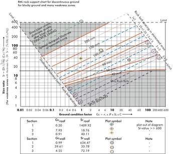
The RMi rock support chart for discontinuous ground with plots of three geological sections is shown in Figure 7.
Rock bolts – The installation of rock bolts as propping agents represents an effective and economical method for the support of rock mass. There are two methods of application in modern tunnelling. Single rock bolts are used to secure small areas of unstable conditions while the use of a systematic rock bolt grid allows the transfer of loads from the degraded tunnel lining to the interior of the stable rock mass. The use of both rock bolt systems was recommended for Poubara.
• Single rock bolts: The use of single rock bolt anchorage for securing small areas with unstable geological condition was recommended during the advance tunnel process. A length no less than 6m was proposed to ensure sufficient traction, mass and strength of the rock bolt.
• Systematic rock bolts: A systematic rock bolt arrangement is required in almost all sections where both soft and hard rocks are anticipated. Spacing and dimensions of the rock bolts are dependant on the prevailing geological conditions. For the systematic bolts systems, either grouted (resin) or Swellex bolts were recommended. Swellex rock bolts are used in hard rocks with a low possibility of fracturing, while the use of grouted rock bolts is recommended for soft rocks and highly fractured areas.
Individual rock bolts and the rock bolt system will be tested at the construction site to ensure appropriate characteristics. The same on-site testing also applies for the rock bolt grouting material.
Shotcrete – To re-enforce the excavated space, shotcrete is applied pneumatically through a hose at constant pressure, directly after the blast. There are two common types of modern shotcrete application; dry mix and wet mix. Shotcrete is reinforced by conventional steel rods, steel mesh, and/or fibres. Fibre reinforced (steel or synthetic) shotcrete is more frequently used for stabilization in modern tunnelling and its use was considered for those project areas where special properties are assigned to the shotcrete, such as fault zones.
Water management
Water inflow in the tunnel – The Lugeon permeability tests performed on drill holes along the line of the tunnel have values of 5 to 10m/sec, indicating low rates of water inflow. Water inflow rates through hard rock are dependant on the spacing and orientation of discontinuities. The geological condition along the course of the tunnel is bedded lithology of siltstone/pelites with intercalation of ampelite and sandstones. Water inflow will circulate along the discontinuities and fractures of the rocks as well as along the stratification horizons. Taking into account the geological conditions, an anisotropic and inhomogeneous groundwater situation for the course of the tunnel was conceived.
The inflow of water is also highly dependant on the time of the year at the Poubara project site. Calculated using the mean pluviometer values of the last 50 years, the months of March, April, May, October, November and December were identified as having high precipitation, with an average of more than 180 mm. Water inflow in the tunnel will be increased during times of intense rainfall.
Risks
Fault zones / decomposed zones – There are possible areas susceptible to higher rates of water inflow. First, the identified major fault zone ‘F5’ represents a brittle zone that permits groundwater to flow more constantly and at higher rates. The same applies in the vicinity of the minor fault zones ‘F3 ‘and ‘F6’. Secondly, zones of strongly decomposed rock also represent brittle areas where water inflow might be increased in comparison to normal conditions. The surface of weathered rock is dependant on the morphology of terrain and lithology. Whenever the excavation of the tunnel is carried out in decomposed rocks, special attention is drawn to appropriate water management. The decomposition of parent rock material leads to the formation of clay minerals and these minerals are capable of blocking and trapping water from circulating along fissures. The result is small-scale confined aquifers which will burst into the tunnel or drill holes when penetrated.
Invert water conditions – The invert of the tunnel is often not specially prepared and consists of extracted loose material. The invert is the base of the machinery and provides work force for the excavation process and is, therefore, subject to changing load conditions. The siltstones, pelites and ampelites may change their consistency and tend to deform after contact with water. The result is a local reduction of the load capacity and interference to the working process due to softening of the invert.
Water management during excavation – A water management system has been foreseen and supports the excavation process. In the event that the water inflow becomes excessive and when it is necessary to reduce water inflow, a grouting programme has been planned. Grouting can be used to seal off the water before excavation. During grouting operations, in front of the excavation chamber and during the curing process, it is necessary to suspended the tunnel advance. This is a disruptive event, as grouting long lengths of tunnel can require numerous weeks of extra effort.
Areas where it may be necessary to grout prior to tunnel excavation include the fault zones ‘F5’, ‘F3’ and ‘F6’ as well as areas of highly decomposed rock mass. Grouting will be initiated at least 10m in advance of the identified brittle zone to assure effective stabilizing.
Surface effect – The construction phase of a tunnel excavated into a complete rock mass system can be regarded as similar to a large drainage system. The discharge of water in near-to-surface tunnels will lead to subsidence at the surface. The impact of this depends on the total discharge of water and on the properties of the lithology. When tunnelling in undeveloped areas, this effect can be neglected.
The crossing of existing developments represents an additional challenge for tunnelling construction. Provisions to minimize surface subsidence must be taken both in advance and during excavation. Preventive measures will include grouting and icing of soft grounds. To evaluate the effect of surface subsidence, extensometer grid systems in combination with a groundwater monitoring system will be installed.
Convergence measurements
During excavation of the tunnel, convergence measurements have been taken and monitoring of deformation to the excavation chamber was undertaken. Deformation of the excavation chamber is a result of stress redistribution leading to increased stress in some parts and a reduction of stress in other areas. Monitoring of this redistribution is necessary to ensure stability of the construction. Convergence monitoring includes in-situ measurements of the excavation chamber, but can sometimes also require surface levelling and the use of surface installations such as extensometer and inclinometer units along the axis of the tunnel.
Arrangement and installation – A standard cross-section for correct data acquisition has been defined for the levelling of the crown and sidewalls to monitor and record deformations. The distance between the single convergence measurement stations must be under 10m. Additional installation of pressure cells in the seam between rock and shotcrete was also recommended to evaluate rock pressure. An additional radial load cell to measure the concrete pressure was also recommended every 50m. A standard cross-section for convergence measurements must be comprised of at least five reading points to ensure complete data acquisition of the crown, the sides and the base of the tunnel cross section (Figure 8). The installation of the reading points must be carried out directly after the installation of the support so as to capture the initial deformation. An early reference measurement must be carried out to assess the later data.
Interval of measurements – The time of the reference measurements has been documented on the Poubara project. The following convergence measurements are carried out quickly and must be executed on a daily basis until the deformation has settled to an acceptable level. The level of tolerance is dependent on the behaviour of the rock mass. Deformations of 5 to 10cm are already critical for a brittle rock mass and might be enough to produce a rock failure while deformations up to 15cm in a ductile rock mass are still non-critical. An evaluation of the fracture behaviour must be assessed to define a tolerable limit of deformation. Once deformation is assessed to be below the tolerance level, convergence measurements can be carried out on a weekly or monthly basis. The time taken for one standard cross-section convergent measurement is typically 10 minutes.
Estimating the tunnelling construction time
General – The main parameters guiding an estimation of tunnelling progress include the available work force (teams, shifts), the machinery and the maximum size of the construction site and its access routes. The normal construction method is from one side only and represents the slowest mode of excavation. The fastest progress can be made by adopting simultaneous excavation from multiple tunnel endings. The geological conditions in the project area favour a two- sided or even a simultaneous excavation from three sides. The main parameter used for the estimation of tunnelling progress is the weekly excavation progress. This parameter was set at 21, 28 and 35m per week corresponding to a daily progress of 3, 4 and 5m.
Construction time estimations – Excavation with one heading face – Daily progress is estimated using the parameters of work force and machinery available for the main tunnelling construction. A constant progress of 3, 4 and 5m per day is expected.
This constant progress can be achieved by two to three shifts per day, with eight to ten hours per shift. The main tunnelling works include the drilling and loading of blasts, scaling of loose material after blasting, mucking, installation of ventilation and drainage units, and the installation of rock supports. The time for completion of the main excavation works for this single sided excavation ranges from 2.52 (3m/day), 1.89 (4m/day) and 1.51 (5m/day) years depending on the daily progress.
Excavation with two heading faces – The time required for tunnelling can be shortened substantially by a simultaneous excavation using two heading faces. The following estimations were made by adopting the same parameters mentioned above. Excavations using two portals can yield time-savings of approximately 50 per cent. The two heading faces are situated at the two tunnel endings with equal sections of approximately 1600 m. The time for completion of the main excavation works for the two sided excavation ranges from 1.46 years (3m/day), 1.09 years (4m/day) and 0.87 years (5m/day).
Excavation with three heading faces – The fastest completion of the tunnel can be achieved by a three-sided excavation. This involves an intensive planning of the construction site taking into account an economic evaluation of the available workforce, machinery and access routes. Two portals are located at the end of tunnel and one additional heading can be installed at the fault, 1800 m from the dam. Each section consists of equal parts of 900 m. Time for completion of the main excavation works for the three sided excavation ranges from 1.05 year (3m/day), 0.84 year (4m/day) and 0.67 year (5m/day) for each heading operation.
Estimation of quantities – Finally, Figure 10 provides estimations of the consumption of different support materials.
Cesar Adolfo Alvarado-Ancieta (Peru), Civil Engineer, Dipl.- Ing., M. Sc., Director of Project, Head Hydropower
Uwe Wackwitz, Maximiliam Riehl (Germany), Dipl.- Geologists, GAUFF GmbH & Co. Engineering KG,
Patrick Yalis Ongalla (Gabon), Ing. Electrical – Deputy Coordinator / Resident Engineer, Direction Générale de l’Energie et des Ressources Hydrauliques, Republic of Gabon, Franceville
External weblinksGAUFF GmbH & Co. EngineeringTablesTable 1