A project to rehabilitate the world’s largest irrigation network is currently underway in Pakistan, with the Jinnah Barrage recognised as one of the network’s most important structures needing rehabilitation. In this research paper Dr Zulfiquar Ali Chaudhry discusses the prospects, and concerns, of the various rehabilitation scenarios suggested for the barrage, and considers their impact on operation and safety
The world’s largest irrigation network consisting of barrages, canals, distributaries and watercourses is located in Punjab, Pakistan. Many of the barrages forming this network are facing hydraulic, structural and ageing problems, and as a result a rehabilitation and modernization project has been launched with financial assistance from the World Bank.
The Jinnah Barrage is one of the important diversion structures recommended for modernization. A feasibility study on the barrage proposed the construction of a subsidiary weir, 800ft (244m) downstream of the barrage as the main rehabilitation structure. Design consultants noted however that the downstream concrete floor is in good condition, while loose stone is deficient in the weir section of the barrage. Impact and friction blocks are intact and are in good health. The Consultants therefore proposed replenishment of loose stone at stable slope as an Alternative 1 to the subsidiary weir. Furthermore, a second stilling basin was proposed in the weir section of the barrage as an Alternative 2. Both solutions were tested on a physical model, developed at the Irrigation Research Institute (IRI), Nandipur, Pakistan.
Subsequently, design consultants proposed a third alternative – a subsidiary weir to be constructed across the river 600ft (183m) from the barrage crest. The existing divide walls will be extended to the bifurcate weir and undersluice sections of the barrage.
The rehabilitation scenarios proposed by the feasibility study and the design consultants would have different hydraulic impacts to the existing structure. The purpose of this research paper therefore is to discuss the prospects and concerns of the various rehabilitation scenarios, and what impact they would have on the barrage operation and safety.
Project details
The Jinnah barrage consists of 42 weir bays, with two undersluices each consisting of seven bays with a clear span of 60ft (18.3m). The barrage width between abutments is 3781ft (1152.4m), whereas clear waterways for weir and undersluice sections are 2520ft (768.1m) and 420ft (128m), respectively. Two divide walls bifurcate the weir and undersluice sections of the barrage. The crest and floor level for the weir and undersluices are at EL678, EL670, EL675 and EL667, respectively.
The barrage has a 20ft (6.1m) wide navigation bay and silt exclusion system in the right and left undersluices, respectively. The barrage is designed for a flood of 26725.6m3; however, a flood of 30945.8m3 can be passed as the barrage guide banks have enough freeboard. Normal pond level is at EL692, which can raise to EL694 to meet the 283.2m3 irrigation requirements of the Thal canal.
Barrage condition
Jinnah barrage has operated for 60 years with no significant incidents. No major structural repair works have been carried out on the barrage, apart from the replacement of impact blocks in 2003. The Feasibility Review Report [9] noted that from 992 to 2006, Rs.106M have been spent on stone replenishment and replacement of 470 impact blocks. Nothing has been spent from 2006 to date. The average annual spending on stone replenishment and the repair of downstream floor/impact blocks is just Rs 5.6M for the last 16 years. This spending does not reflect the severity of the situation described in the Feasibility Report [8].
Some retrogression is always anticipated downstream of a barrage. The Alternative Report [7] noted that in the past 17 years no further retrogression has occurred. The Feasibility Review Report [7] and Chaudhry [2] stated that in the weir and undersluice sections, the stilling basin floor and impact blocks are intact and in good health. However, the loose stone apron downstream of the stilling basin is deficient in the weir section and needs replenishing, while it is almost adequate in the undersluice section.
Energy dissipation concept at Jinnah Barrage
The weir section of the barrage has crest and floor levels at EL 678 and EL 670, respectively, whereas the corresponding levels at the undersluices are EL 675 and EL 667. The Alternative Report [7] noted that the stilling basin floor should be at EL 664 to develop hydraulic jump on glacis, indicating that the existing level is up by at least 6ft (1.8m). Furthermore, if retrogression of 7ft (2.1m) is assumed, then the floor will be at EL 662. The Feasibility Report [8] noted that the subsidiary weir stilling basin should be at EL 659, indicating that the barrage stilling basin is up by 11ft (3.4m).
It is pertinent to mention here that the length of the downstream glacis is 24ft (7.3m) [1:3 slope], which is inadequate to keep hydraulic jump on it. Even if the stilling basin floor is assumed at EL 664, the length of the glacis will be 42ft (12.8m). Deficient glacis length cannot be addressed without lowering the stilling basin floor level. Therefore, the Jinnah barrage energy dissipation system cannot be categorized as jump type; rather it is impact cum jump type. Chaudhry [4] noted that at Jinnah barrage the downstream water depth was not adequate to keep hydraulic jump over glacis even in 1948 – the year the barrage started operation.
The energy dissipation mechanism at Jinnah barrage consists of a stilling basin and two rows of impact blocks, where two rows of friction blocks are placed as an end sill. Chaudhry [3, 4] noted that the arrangement is efficient and is not very sensitive to downstream water depth. If water depth becomes less than the conjugate depth, the impact blocks take the impact of water and divert it up. Energy dissipation takes place partly in air and partly in water, whereas friction blocks help in controlling water depth and allowing shingle to pass.
Underneath the floor the soil strata consists of consolidated shingle, which was difficult to excavate at the time when the barrage was constructed. It seems that an impact cum jump type energy dissipation system was designed to save this excavation effort.
Rehabilitation solutions
A rehabilitation solution should precisely address hydraulic/structural design deficiencies existing at a barrage. Furthermore, the proposed solution preferably should not change the hydraulic design concept on which the energy dissipation system for a particular barrage/head regulator is designed. If the energy dissipation concept/mechanism does change, than it must be deliberated, otherwise the intervention could be disastrous.
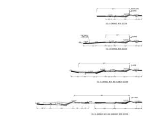
Subsidiary weir
As stated earlier, the subsidiary weir proposed by the Feasibility Report [8] would be constructed across the river, 800ft (244m) from the barrage crest. The elevation difference between the barrage and subsidiary weir crests is just 2ft (0.6m) [Figure 2]. The barrage’s right undersluice crest is lower by 1ft (0.3m) as compared with the subsidiary weir crest level. However, in front of the left undersluices, the subsidiary weir crest level was kept at EL674, with the upstream water level controlled by mechanical gates. Two fish ladders and a navigation bay were also proposed through the subsidiary weir. Figure 2 and Table 1 show that the structure is even larger than the existing barrage.
The Alternative Report [7] did propose two substitute solutions to the subsidiary weir, but detailed design consultants finally submitted a rehabilitation solution where the subsidiary weir was to be constructed 600ft (183m) from the weir crest (Table 1). The existing divide walls have to be extended to bifurcate the weir and undersluice sections of the barrage, which will develop three separate channels between the barrage and the subsidiary weir. Either of the subsidiary weirs would change the hydraulic design concept for energy dissipation system at the barrage.
Hydraulic and financial aspects of subsidiary weirs
Chaudhry [3] and the Alternative Report [7] studied hydraulic jump development with subsidiary weir and noted that the Froude number remains less than 2.5 for most of discharges, indicating weak and unstable hydraulic jump. Jump became undular at the discharge of 842,000m3/sec. Downstream velocity remained greater than 9ft/sec (2.7m/sec) at higher discharges, showing that the proposed weir cannot reduce displacement of the loose stone apron.
Chaudhry [3] further noted that at the undersluices hydraulic control was shifted at the subsidiary weir as its crest level was higher than the corresponding crest level of the undersluices. This would mean that the discharge capacity of the undersluices and the efficiency of the silt exclusion system would be badly affected, and the existing guide banks would have to be raised to pass a design flood of 950,000m3/sec.
Table 1 shows the water depth downstream of the barrage for various rehabilitation scenarios studied in the physical model. The increase in water level upstream of a subsidiary weir placed either at 600ft (183m) or 800ft (244m), with crest at EL676 was not promising, especially at higher discharges [10]. The increase in water depth was just 2.25ft (0.7m) at the discharge of 950,000m3/sec. It is already known that for a jump type-stilling basin, prevailing water depth is deficient by 8ft (2.4m). This demonstrates that the change in energy dissipation concept from impact to jump is not convincing at Jinnah barrage.
Decrease in velocity upstream of the subsidiary weir, especially at higher discharges, is also not promising. Furthermore, the velocity remained fluctuating and higher in regions where the stone apron is placed. Chaudhry [10] noted that deep scour pits developed and the stone apron was completely washed away (Figure 3a). As shown in Figure 3b, the situation became worse when compared with the existing condition.
Silt exclusion may be needed on the right side of the barrage to meet future anticipated changes in the pattern of flow feeding the Jinnah hydro power project. Its construction and operation will be difficult with the addition of a subsidiary weir. During high flow, shingle may move along with the water, being deposited between the barrage and the subsidiary weir. Furthermore, massive Ballas has developed downstream of the barrage. The discharge capacity of the barrage may reduce in the presence of Ballas and the subsidiary weir, which could result in an increase of the upstream water levels.
Construction of divide walls in the scoured area itself is a massive job. Any failure of divide walls could be catastrophic, as the flow will be oblique and may change the river route. Furthermore, the repair and maintenance of two independent structures, as well as stone apron replenishment at three locations, would be expensive. It suggests that a subsidiary weir 800ft (244m) or 600ft (183m) from the barrage crest may have serious hydraulic concerns if constructed.
Either of the subsidiary weir arrangements would be larger, and costlier than the existing barrage. Table 2 shows the salient dimensions of subsidiary weirs, various rehabilitation scenarios and the barrage itself.
Loose stone apron at stable slope
The Feasibility Report [8] and Alternative Report [7] noted that the loose stone apron downstream of the concrete block floor displaces excessively at Jinnah barrage. Presently, the loose stone apron is placed at EL670, which will be at EL662 if designed as per USBR guidelines. Velocity and kinetic energy remains higher and the stone apron will be launched if not placed in the proper size and at a stable slope.
One possible solution could be the extension of a concrete block floor at the slope of 1:5 for a length of about 25ft (7.6m); allowing the loose stone apron to be placed at a lower level. The Alternative Report [7] proposed a loose stone apron at the slope of 1V:15H, which starts from the concrete block floor (EL670) and ends at EL662. This arrangement makes the barrage safe from ill effects of retrogression, scouring and launching of the stone apron. The proposal was tested on the physical model (Figure 4) and it worked well for gated and ungated flow.
Furthermore, the stone apron finishes within the existing divide walls without affecting the function of fish ladders. It is a logical, economical and hydraulically suited solution.
Two-step stilling basin
Instead of filling the scoured area with stone, a second stilling basin could be added just at the end of the existing concrete block floor (Figures 2 and 5). The additional stilling basin will act as an integral part of the existing barrage. In this arrangement a cumulative hydraulic performance of both the basins is to be considered.
The second stilling basin floor may be fixed at EL659, which was the same as for the subsidiary weir proposed by the Feasibility Report [8]. Furthermore, the end sheet pile was proposed at EL648, which protects the stilling basin from the ill effects of local scouring and retrogression.
A concrete block floor with inverted filter to mitigate seepage and uplifts could be developed underneath the existing barrage and proposed structure [7]. An end sheet pile, along with inverted filter arrangement overlaid by concrete block floor, could control seepage, uplift and movement of fines. Gaps could be provided through the weir to facilitate shingle movement along with water.
Furthermore, the arrangement finishes within the existing divide walls and will not change the function of the undersluices and fish ladders. This arrangement also avoids the possibility of piping underneath the barrage. The proposal was tested on the physical model and it worked well. It is more expensive than stone replenishment, but may be provided if needed.
Conclusions
The Jinnah barrage downstream glacis length is 24ft (7.3m) (1:3 slope), which is inadequate to keep hydraulic jump over it. Deficiency in glacis length cannot be addressed without lowering the stilling basin floor level. Therefore, the energy dissipation system at Jinnah barrage cannot be categorized as jump type; rather it is impact cum jump type.
Various rehabilitation scenarios are discussed in terms of their hydraulic functioning and financial impact. A subsidiary weir either at 600ft (183m) or 800ft (244m) would not have any hydraulic/structural significance; instead it could result in the further launching of loose stone. An extension of the divide walls will develop three channels between the barrage and subsidiary weir, and their construction would be challenging as deep scour pits already exist. Failure of divide walls could be catastrophic, as repair work would be very difficult.
The replenishment of the loose stone apron at the launching slope is a more hydraulically suited and economical rehabilitation solution and may be adopted at the Jinnah Barrage, although the provision of a second stilling basin in the weir section of the barrage would also be an efficient rehabilitation solution. Since it can be completed within the existing divide walls; the functions of the undersluices, fishladders and navigation bay may not be affected. It is more expensive than stone replenishment but could be utilised if a more permanent solution is needed.
Dr Zulfiquar Ali Chaudhry, Professor, Civil Engineering Department, University of Engineering & Technology, Lahore
The author is thankful to Mr. Shakoor, Senior Model Expert, for technical discussions and valuable suggestions