Ram Hari Sharma presents a case study of Middle Marsyangdi hydroelectric project in Western Nepal and describes the tunnel excavation technique using steel pipe canopy where the ground condition is loose, unconsolidated or exceptionally poor rock mass
Middle Marsyangdi Hydroelectric Project the second largest hydroelectric project in Nepal, lies in the middle reaches of the river Marsyangdi in the district of Lamjung in western Nepal. The construction of the 72MW project started in early 2001 and is expected to be completed by the middle of 2007. The major components consist of: a 95m long and 62m high concrete gravity with part rockfill dam; three intake tunnels to three different underground desilting chambers; a power tunnel 5.2km long and 5.4m finished diameter; a 57m deep fully underground surge tank of 21.3m finished diameter – the biggest underground shaft in Nepal; a 224m penstock tunnel of which the last 96m passes through loose landslide colluvium debris deposits; a 226m long exposed inclined penstock to the power house; and a semi-underground power house with a very short tailrace outlet to Marsyangdi river.
The project is located about 10-15km south of the main central thrust (MCT) and about 50km north of the main boundary thrust (MBT). These major tectonic boundaries are trending in an East-West direction and dip gently north. Quartzite, phyllite and phyllitic quartzite of Kuncha Formation are the main rock type of the project area. The Marsyangdi valley was created by the Marsyangdi river; it has eroded a deep and partly canyon like valley from north to south and mostly through metamorphic bed rock. The project area is located at an elevation of 500-700m in a zone where the valley is wide and characterised by large accumulations of Quaternary and recent terrace deposit which is mainly comprised of alluvial materials, mudflow deposits and moraines. The Quaternary soils cover the most important part of the project area. Fluvial, mudflow (glacio-fluvial), colluvium, talus deposits and residual soil are representative for these soils.
The project area is within a 7km range where a 5.2km long power tunnel has been excavated through the meta-sedimentary rocks of Kuncha Formation. The rock mass encountered during power tunnel excavation is predominantly phyllite, phyllitic quartzite, phyllitic schist and quartzite. The rock mass classification carried out during the tunnel excavation varies from very poor to fair rock mass quality, however the end section of the penstock tunnel passes through exceptionally poor geological condition having a landslide zone with colluvium debris deposits. This paper focuses on the tunnelling technique through such poor geological conditions.
Tunnelling methodology
The tunnel excavation and support at Middle Marsyangdi was carried out following the New Austrian Tunnelling Method (NATM). This method uses the advantage of the rock’s capability to support itself, by careful measures and deliberate guidance of the forces during the re-adjustment process from the primary to secondary state of stress-strain which takes place in the surrounding area of the excavation. The rock mass will be able to support the stress-strain as long as local progressive loosening will be limited by rock support like shotcrete and rockbolts. In more jointed rock mass the shotcrete has to be reinforced by steel mesh or steel fiber and the length and number of rock bolts have to be increased. In the fault zones it may become necessary to use rockbolts and rock anchors in order to improve the triaxial state of stress in rock mass itself, enabling the support to withstand the secondary shear stress. The application of the NATM requires deformation monitoring and measurement by means of survey and special devices.
Tunnelling for the last 100m portion of penstock tunnel, however, was carried out using a special tunnelling technique utilising steel pipe canopy (pipe umbrella arch grouting).
Penstock tunnel alignment
The project’s penstock tunnel is 224m long. According to the detailed geological report for the project, the penstock tunnel alignment requires an underground crossing through poor to fair rock mass quality of slightly weathered heavily jointed phyllitic quartzite up to the outlet portal. The initial design did not predict any other conditions.
During excavation of the penstock tunnel, from the valve chamber to the downstream, the geological condition was found to be significantly different from that anticipated in the report. The last 100m underground crossing to the outlet passes through an exceptionally poor geological condition, landslide zone of colluvium debris deposits. The support class defined in the report was found to be unsuitable for such conditions. The longitudinal geological profile of the surge tank and penstock tunnel alignment showing the assumed rock line at the tender stage and the actual rock line conformed during the construction is shown in Figure 3.
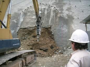
It was thus concluded that the tunnelling for this section had to be carried out by means of mechanical excavation with pipe roof umbrella system combination with various other support like shotcrete, steel rib, steel girder and IBO bolts (shelf drilling anchor). As the geological condition has been almost loose landslide debris deposits, a mechanical excavation method using a tunnel excavator was adopted. Blasting was strictly prohibited to minimise the risk of collapse due to vibration and loosening the mass. Local blasting has been carried out in case of the presence of large boulders. The pipe roof umbrella system was designed 12m long with 15 steel pipes at the crown above the Spring Level (SPL) for an 8m round of tunnel excavation with a 4m overlap in the next round. Grouting through the installed pipe is followed during the pipe installation. After the completion of the pipe installation and grouting, a tunnel excavator carefully excavated the tunnel. A thin layer of protection shotcrete was applied at the crown and wall to protect against any collapse before installation of the full support. The main use of protection shotcrete was to increase the stand up time until the additional support is applied. Elephant foot full face steel rib and steel fiber reinforced shotcrete was applied as quickly as possible after each excavation advance, followed by installation of IBO bolts, weep holes and closure of the invert by reinforced shotcrete.
Installation of the Pipe Canopy
The AT (Alwag Techmo) casing system from Techmo Austria is adopted but the drilling accessories were from Sandvik and steel pipe brought from China. Atlas Copco Boomer 282 has been used with simple modification for drilling and installation of the canopy pipe. The steel pipe itself is 88.9mm (outer diameter) with wall thickness of 4.5mm. The distance between installed pipes at the crown is 50cm. The pipe canopy which consists of closely spaced, grouted, steel tubes worked effectively and significantly controlled deformations and volume losses for wide range of ground conditions. It reduced dilation since grouting bound in the loose mass and colluviums materials improved face stability and increased stand-up time. The pipe roof umbrella system is 12m long for 8m tunnel excavation with 4m overlap with the next round of pipe canopy for further excavation work. Tunnelling was carried out gradually increasing the section from 1 to 8m (in 8m long sections) of each round. The last tunnel section is expanded 1m in diameter. The bigger section at the end of 8m round is needed to install the next round pipe canopy at the crown through the design line.
The ODEX method drilling principle was used to install the pipe canopy. This method allows for the simultaneous drilling and lining of deep holes with steel pipes in all type of geological condition. An important feature of the ODEX system is that the steel pipe does not rotate during driving. This makes it possible to install the pipe canopy without the need for torque or rotation of the pipe. It also makes it possible to use low price thin wall casing tubes for pipe canopy. When the steel pipe (canopy pipe) reaches the desired length, drilling stops and reverse rotation is carefully applied. This system causes the reamer to swing on, reducing the diameter of the drill bit assembly. When this has been done the entire drill-string can be pulled out leaving the steel pipe inside the ground at the tunnel crown for grouting. Installation of pipe canopy in an accurate angle was one of the important tasks of this method and it was carried out very successfully at this project.
Grouting
Cement grouting was carried out through the outer end of the installed pipe. Perforated holes drilled around the installed pipe help to dissipate the cement slurry into the ground around the pipe at the crown. The applied grouting pressure was fixed at 3 to 4 bar depending up on the ground condition and the water cement ratio of grout mix was 1:1 to 1:2. During grouting it was insured that the minimum effective area of grouting must be 50cm around the pipe and the pipe itself should be full of cement grout. The 50cm effective range of grouting around each pipe made an improved umbrella arch at the crown and the fully grouted steel pipe took the load of loose overburden. The grouting was limited as per geological condition at site because this is not a mass grouting – it is only for improving the ground condition of the tunnel crown. An excess grouting can be a problem as grout flowing down to the face can be a problem for excavation and extra cement consumed unnecessarily. Atlas Copco Craelius grout pump – also called the Unigrout (combination of Cemag, Cemax & ZBE) -was used for grouting.
Excavation
After completion of the installation of the pipe canopy and grouting, excavation work was started. A mechanical excavation method was adopted for tunnel excavation with the use of the Liebherr 912 tunnel excavator with 1m advance. Blasting was strictly prohibited due to poor geological condition and to minimise the risk of collapse due to vibration and loosening of the mass. Local blasting was carried out in case of the collapse of large boulders. Full-face excavation was initially completed by a tunnel excavator with 1m advance and support up to 8m. When the 8m tunnel excavation was completed with full support, the next round of pipe canopy installation and grouting was carried out for next round of 8m excavation and support. However the full face excavation was possible only in dry conditions with applied initial protection shotcrete immediately after the excavation at the exposed crown and wall before mucking. The initial protection shotcrete support increased stand up time and allowed mucking and subsequent support.
The condition was under control with full-face excavation up to 30m inside the portal but onwards the mass flow started from the face extending towards the crown because of groundwater seepage from the face and wall. The presence of groundwater and associated seepage pressure adversely affected the stability of tunnel excavation. When the geological condition is completely loose with groundwater the mass starts to flow and may collapse the pipe roof umbrella. In such conditions very careful judgment is needed to control any collapses.
Because of this it was decided to close the face, with protection carried out by dumping the boulder, gravelly muck at the face and sealing it with thick wiremesh shotcrete. During the face sealing the seepage water was release through the pipes, which were then covered by shotcrete. The outlet of the pipe was kept open to flow the water. After sealing the face, long drain holes were drilled at the face to drain the groundwater.
After discussions among the tunnel engineers about the procedure for further advance, it was decided to go ahead with Top Heading and Benching.
Top heading excavation
When the full face excavation was felt to be too risky due to groundwater seepage and mass collapse, excavation was done by top heading and benching method. The top heading excavation was carried out part by part, gradually opening the left part of the crown and providing immediate protection shotcrete, The right crown was then opened followed by protection shotcrete. Immediately after the excavation of 1m top heading it was supported by lattice girder and shotcrete. The excavation was carried out by a tunnel excavator. The removal of some materials below the pipe canopy was carried out by small pneumatic cutting hammer. The lattice girder and shotcrete at the arch of heading was applied before benching and installation of steel rib with final SFRS support. The benching was 4m behind the top heading with full face steel rib and final support.
Bench excavation
Bench excavation was relatively easy compared with the top heading, but the excavation was carried out by tunnel excavator very carefully in case the side walls collapsed. If these walls did give way, the girder support of the crown could hang and also affect the pipe roof umbrella. The protection shotcrete was applied immediately before full-face steel rib erection and shotcrete support. Similarly the excavation was completed up to the end following the same process as the top heading.
Rock support
The rock support is needed to improve the stability of the excavated tunnel. The rock support should be applied in accordance with the actual ground condition encountered during tunnel excavation. This requires flexible support which can be quickly applied within the limited time and should meet the adjustment for continuously changing rock mass quality and behavior. Such flexibility has been achieved at the penstock tunnel with the use of a pipe roof umbrella (pipe canopy) system including the combination of various other support like shotcrete, steel rib, steel girder and IBO bolts (shelf drilling anchor).
Installation of pipe roof umbrella and grouting before excavation, 50mm thick protection shotcrete immediately after the excavation of each 1m advance, steel rib support at 1m c/c, 30cm thick steel fiber reinforced shotcrete at wall and arch, 20cm thick shotcrete with two layer wiremesh at invert and Self Drilling Anchor (IBO Bolt) at 1m c/c below the pipe canopy are the applied support combination of the penstock tunnel. This combination provides immediate stabilisation of an opening as well as permanent stabilisation.
Pipe roof umbrella
The umbrella arch which consists of closely spaced, drilled and grouted steel tubes of >90mm at the tunnel crown is effective in controlling deformation, any collapse and volume losses for a wide range of ground conditions. The grouted pipe roof reduces the dilation in soft ground condition; improves face stability and increases stand up time for excavation and helps in applying other subsequent support.
Shotcrete
Shotcrete (spraying concrete) on excavated wall and arch of the tunnel for rock support is the most important flexible rock support for any type of ground condition. In the project’s penstock tunnel the shotcrete was applied in three different shotcrete methods.
* Ordinary shotcrete (Dry) and protection shotcrete sprayed up to 50mm thick immediately after the excavation or before mucking applied by simple manual dry shotcrete machine (CP5 Condur, made in China).
* Fiber reinforced shotcrete that was needed as structural shotcrete 300mm thick at wall and arch. The wet mix steel fiber reinforced shotcrete (SFRS) was robotically applied by MEYCO Robo-jet.
* Mesh reinforced shotcrete, 200mm thick ordinary shotcrete with two layer wiremesh was applied at the invert for invert closure after completion of steel rib support covered by 300mm thick SFRS.
Steel rib support
Steel rib support was applied after the excavation and protection shotcrete at 1m c/c in every round excavation. The steel rib support is very important for immediate load transfer. It was in five segments jointed by bolting which is quick in erection and easy to handle manually and machine during the erection. The steel rib was erected at the proper location maintaining the design line and length with the help of a tunnel excavator.
Rock bolt
Rock bolting is a very common flexible rock support to anchor the fractured rock mass in the tunnel and gives the strength and stability to the ground. Since the ground condition was completely loose and the drill holes collapsed immediately during the drilling, it was not possible to apply the pre-grouting SN rock-bolts. Therefore the Self Drilling Anchor and post grouting method was applied. The Self Drilling Anchor and post-grouting method is relatively costly than pre-grouting SN rock-bolts but it was the demand of ground condition of penstock tunnel.
The self drilling anchor (IBO bolt) was used below the pipe roof umbrella. The IBO bolts used were 6m long and 32mm diameter fully threaded and hollow in center to send the cement grout through it. Figure 8 shows the plan and section of arrangement of the self-drilling anchor.
Weep hole
Weep holes were drilled to release the water pressure from the ground to improve the stability of the ground. At the penstock tunnel 48mm diameter and 6m long weep holes were drilled in a systematic pattern.
Monitoring and Measurement of the tunnel
Monitoring and measurements of the tunnel was essential to discover the behavior of the ground condition. This method/information is a feedback for the adjustment of support design and is a precautionary measure in case remarkable deformations were discovered inside the tunnel.
Therefore, the following monitoring and survey measurements were carried out during the excavation and support at the penstock tunnel.
* Inclinometer above the portal slopes
*Convergence measurement and crown settlement measurement inside the tunnel
* Monitoring groundwater condition
Construction schedule
According to the contract agreement the construction schedule was 196 days with two shifts covering 24 hours. However, work was completed 59 days ahead of schedule. The average progress per week was 5m including drilling/installation of pipe canopy, grouting, excavation by top heading and benching and full support with invert closure. Figure 9 presents the excavation and support progress chart. Moreover, during the excavation, extra time was taken to stabilise the face collapse, side wall collapse and sometime collapse of applied shotcrete with loose mass due to ground water.
Author Info:
Ram Hari Sharma is Senior Engineering Geologist at Himal Hydro and General Construction Ltd. Email: rhsharma.egs@himalhydro.com.np