The combination of better design and the use of protective coatings is an effective way of reducing abrasive erosion of hydro power turbines, say M. Engelhardt and D. Oechsle
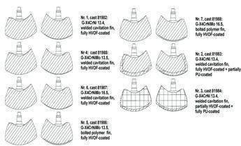
Figure 6
HYDRO power plants located on rivers where the content of abrasive materials reaches extremely high seasonal levels have to deal with the severe situation of hydro abrasive erosion. Silt erosion is still a major obstacle to the economical exploitation of hydro resources.
Over the past few years, voith-siemens Hydro Power Generation, together with partners from all over the world, has carried out examinations to try to overcome this problem. The San Men Xia power plant in Henan province, China, was chosen for a joint research and rehabilitation project. The aim of the project was to formulate a comprehensive programme of up-to-date measures against silt erosion.
Apart from catchment area treatment (CAT) and other measures to reduce the amount of sand and silt going through a hydraulic unit, suitable solutions have been found to fulfil the requirements of reducing damage to hydraulic components thus reducing maintenance costs of hydro turbines.
A process was developed to modify the hydraulic shape of turbines to reduce hydro abrasive erosion significantly, particularly by avoiding wear ‘hot spots’. These measures reduce erosion but do not completely prevent it. As existing units cannot be protected by design changes without carrying out rehabilitation work, a material-based solution to protect the surface of hydraulic components was also examined. Material tests were done to examine available base materials and coatings to obtain a rating about wear-related properties. The material examinations led to two different solutions which have already shown their potential on pilot and commercial projects.
State of the art
More than 20 years ago, a system was established by Voith Siemens Hydro to calculate the expected lifetime of hydraulic components operating in silt-laden water. By changing the hydraulic, sand and silt parameters the effects on lifetime can be calculated. Calculations were based on interpolation of empirical data and the results gave an idea about erosion but were not sufficient. Using this programme, it was not possible to differentiate between high and low affected areas on a single component like a runner. To improve the prediction of hydro-abrasive wear, and also to find suitable solutions to reduce it, a research project was started. The project was divided in two parts; the establishment of a numerical tool to determine wear on hydraulic components, and the examination of different materials and coatings to protect the hydraulic surface.
Erosion prediction
As explained in Schneider & Kächele (1999) hydro-abrasive wear is commonly quantified by means of a wear rate W, defined either as loss of mass or increase of erosion depth per unit time. A number of experimental investigations have shown that W is a function of a multitude of parameters, shown in the following algebraic relation:
W ~ c q f(d50) vn [1]
where W (kg/hr) = wear rate; c (kg/m3) = sand concentration; q (kg/kg) = hard particle contents; d50 (m) = median particle size; v (m/sec) = flow velocity; n (-) = exponent
Besides the linear influence of the sand concentration c, it is obvious that W also depends on the hard particle content q. The assumption of this linear influence, however, is already a compromise which is not suitable to describe the complete influence of material parameters. Another parameter of hydro-abrasive wear is the size of the impinging particles which shows a non-linear influence. As the kinetic energy of a particle increases with its diameter it is easy to imagine that the extent of wear will also increase with particle diameter. Experiments prove this idea up to a limit of particle size above which the erosion rate becomes constant. But very fine particles may also have a harmful effect as they are able to follow the turbulent movement of the flow.
The well-known over proportional influence of flow velocity v is described by means of the exponent n. The value of n was determined in multiple experiments and varies considerably from about 2.1 to more than 3. This range of values again reflects the limitations of the algebraic relation above, which considers neither the material parameters of the eroded body nor the flow parameters or the various material parameters of the silt particles. An advanced approach to the estimation of erosion wear therefore requires much more specific data, which allows the formulation of a differential erosion wear law to consider particular flow conditions as well as the damage mechanism of a specific sand/surface material system, (Schneider & Kächele, 1999).
Optimisation of hydraulic design using numerical fluid simulation tools is an essential part of the manufacture of hydro turbines. These computer programmes can solve the Navier-Stokes equation within a given hydraulic design. The 3-dimensional flow and pressure distributions of the hydraulic systems are calculated.
With knowledge of flow conditions, the trajectory of particles can be calculated (see Figure 1). The sand conditions of a project can be transferred to the numerical system. The number and impact parameters can then be calculated using the numerical tools. However, to calculate accurate wear rates based on the impact information, the adaptation of existing computational fluid dynamics (CFD) tools is necessary. In particular, the behaviour of different materials under hydro abrasive conditions has to be transferred to the module of wear prediction. Even without the material based calculations, the CFD tools are able to estimate wear rates, based on hydro abrasive erosion.
Areas where the wear rate reaches extremely high values are indicated in Figure 2. Design changes can be performed at this stage and modifications can be applied during the design process. The main effort is to avoid wear ‘hot spots’ and to get a balance in hydro abrasive erosion on the hydraulic surface of the component. Optimising design also leads to a reduction in the risk of failure by local hot spots.
Erosion protection
Apart from erosion prediction, which is suitable for new hydraulic designs and rehabs, a solution to protect new and old turbines is necessary. Another part of the research project was to select protective coatings to be applied to the pilot unit. This selection was based on extensive laboratory work. A test piece of equipment called a slurry pot and a high velocity test rig were used to qualify the different materials and coating techniques. A survey of more than 60 different samples provided a clear view of what can be achieved with these materials.
Schneider (1998) and Schneider & Kächele (1999) showed that progress in other fields of technology have led to the development of coating materials which offer significant improvements in erosion resistance of hydraulic components.
Two groups of materials, relying on completely different protection mechanisms, clearly dominated the top end of this classification. The first group is ‘CerMet’ coatings, thermal sprayed two-phase layers of ceramic hard particles, embedded in a metal phase, and applied by the High Velocity Oxygen Fuel (HVOF) thermal spray process (used to apply ‘hard’ coatings such as carbide / metal matrix systems). In this process the exhaust gases of an oxygen flame are accelerated to transonic speed by a burner chamber shaped as a nozzle. The dense coating layers which result are characterised by high bond strength and extraordinary good wear resistance.
The other group is a new generation of polyurethane polymers, which showed extremely low wear rates during tests. Application of these coatings requires careful surface preparation similar to that prior to HVOF coating; degreasing and blasting to a certain degree of roughness are the main requirements. The actual application techniques are generally based on conventional varnishing technology.
Based on the tests mentioned above and other examinations, two materials, one from each group, were selected for pilot applications. A hard, HVOF-applied TC/CoCr coating, named Diaturb 532 and a soft PU-based coating called Softurb 80 were chosen to protect the pilot turbine and its components.
Table 1 shows the advantages and disadvantages of the two different systems; depending on the conditions, one technique or even a combination of both as shown in Figure 3 will lead to the required results.
Countermeasures against wear
Experience at San Men Xia
The San Men Xia hydro power plant in China’s Henan province was chosen for full scale testing of the improvements found during the research programmes. As the conditions in the Yellow river, where the facility is located are very severe, the applied protection systems were to be tested under extreme conditions. Before the rehabilitation of unit 1, the average interval between overhauls was about 10,000hr, including the flooding season. The option to stop the unit during the flooding season led to an unacceptable loss of generation of about 300GWh per year.
Mechanical design
The mechanical design of the runner was changed. Instead of eight blades, the new design had only seven. The diameter of the discharge ring was increased to 6100mm and a full spherical discharge ring design was chosen. The application of these measures led to a reduction of the flow velocity inside the turbine and also to the minimisation of the gap flow between discharge ring and runner blades. The wear reduction was calculated to be 15% compared to the original design, without having erosion hot spots.
Applied protection techniques
Material-based protection techniques were also applied on the unit. Both the hard and soft coating systems were used, sometimes in combination with each other. The protection system on the runner blades was varied not only by using different base materials but also by the applied protective coatings.
Results
The San Men Xia research project included a monitoring phase of two years, during which the turbine parts were inspected several times. In general the measures adopted met the demands. Because of the combination of design optimisation and erosion protection, individual effects could not be determined.
Except for some mechanical damage to the protection systems, wear rates on the HVOF-coated runner blades were determined to be within the accuracy of the thickness measurement gauge (<40µm). The wear rate on the PU-coated surface of the runner blades and the guide vanes was determined to be around 0.15mm per year. The unit was in operation during the two-year monitoring phase and also during the flooding season with an average sand concentration of 20–30kg/m3.
Local damage at the leading edges was found on all runner blades and guide vanes as well as small localised damage to other components. This was not caused by wear but by the impact of large stones and other objects in the river water. An important consideration is that the intake of unit 1 does not have a fully intact trash rack, and that the river bed is almost on the elevation of the unit intake itself so bed load and other flotsam can easily enter the turbine. Stones, small trees and even a steel plate were found in the spiral case of the unit. During the monitoring phase, improvements were done to reduce the damage caused by large particles. After one flooding season, the protection system still worked fine at the guide vanes, but due to the high relative velocity at the runner blades, the coating was not able to withstand the high forces there. Some delamination also occurred on the coated surfaces, caused by the application process which was therefore already improved.
Overall the research project produced interesting results. Rates of wear at the new designed and protected surfaces were minimal compared to the original runner parts. The experiences were included in a process of improvement for the protection systems.
Conclusion
The results in erosion prevention and protection, especially at the San Men Xia project, indicate that minimising erosion can only be reached by combination of design optimisation, based on erosion prediction, and protection of surfaces with wear reducing coatings. The optimisation in design leads to a balanced erosion attack on the surface of wet hydro turbines components. An optimum between wear reduction and the efficiency and output can be found by iteration.
Unfortunately these combined measures are only applicable to new designed turbines and, with some restrictions, to rehabilitation projects. The application of only the erosion protection materials without design changes can be done at new runners and components as well as rehabilitations or even at existing components in situ.
The combination of both countermeasures will lead to a very significant reduction in hydro abrasive erosion, thus improving the economical operation of hydro power plants operating in silt laden water.
Author Info:
M Engelhardt and D Oechsle are with Voith Siemens Hydro Power Generation GmbH, Heidenheim/Germany
For more information email: Michael.Engelhardt@VS-Hydro.com
The project was carried out with financial assistance from the German government (MaTech – Forderkennzeichen 03N2010/1)