A test loop for Korea’s SMART integral pressurized water reactor aims to investigate system performance and thermal-hydraulic phenomena occurring during normal, abnormal, and emergency operating conditions. By Hyun-Sik Park, Sung-Jae Yi and Chul-Hwa Song

In 2012, the Korean Atomic Energy Research Institute (KAERI) completed construction of a new test facility for its 100 MWe SMART reactor, which gained Standard Design Approval (SDA) from the Korean regulatory body in July 2012.
In the 300MWt SMART design, the main components including a pressurizer and steam generators are installed in a reactor pressure vessel without any large-size pipes. The safety systems are simplified, as a Large-Break Loss of Coolant Accident (LBLOCA) scenario is inherently excluded. The SMART design also adopts a modular-type configuration, and offers various advantages in diverse applications such as co-generation and desalination.
The SMART-ITL facility was designed to simulate the integral thermal-hydraulic behaviour of the SMART reactor. The integral-effect test data will also be used to validate the related thermal-hydraulic models of the safety analysis code such as TASS/SMR-S, which has been used for the performance and accident analysis of the SMART design.
SMART-ITL facility design
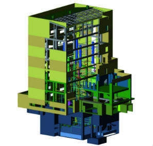
The SMART-ITL facility has been designed following a three-level scaling methodology.
Its height is preserved to the full scale, and its area and volume are scaled down to 1/49 compared with the prototype plant, SMART.
The maximum core power is 2.0 MW, which is about 30% of the scaled full power, generated by electrical (non-nuclear) heaters. The design pressure and temperature of the SMART-ITL facility can simulate the maximum operating conditions of the SMART reactor, that is, 18.0 MPa and 370°C.
The SMART-ITL consists of a primary system, four steam generators (SGs), a secondary system, four trains of a passive residual heat removal system (PRHRS), four trains of a safety injection system (SIS), two trains of a shutdown cooling system (SCS), several break simulators (BS), a break flowrate measuring system (BMS), and auxiliary systems.
Safety systems
The passive residual heat removal system (PRHRS) is composed of four trains, each of which includes an emergency cool-down tank (ECT), a heat exchanger (HX), a makeup tank (MT), several valves, and connecting pipes. It is connected to feedwater and steam lines of the secondary system, and a natural circulation flow path is formed by opening the PRHRS isolation valves and closing the secondary system isolation valves following the PRHRS actuation signal. It is designed to have the same pressure drop and heat transfer characteristics and arranged to have the same elevation and position as those of SMART to preserve the natural circulation phenomenon. In addition, the diameter, thickness, pitch, and orientation of the heat exchanger tubes of the SMART-ITL facility are the same as those of SMART.
During the PRHRS operation, the superheated steam generated from the steam generator secondary side is directed to and condensed in the PRHRS heat exchangers by natural circulation. The condensed water flows downward through the PRHRS condensate line and returns to the feedwater line. The condensing heat is transferred to the ECT, which is filled with the water and functions as an ultimate heat sink.
The safety injection system (SIS) and shutdown cooling system (SCS) can simulate several operation modes such as charging, letdown, spray, safety injection, long-term cooling, shutdown cooling, and recirculating operations. The break simulators (BS) consists of a quick-opening valve, a break nozzle, and instruments. The break measurement system (BMS) has a function to collect the break flow and maintains a specified pressure to simulate the back-pressure of the containment, if necessary. A separator in the BMS separates a liquid phase from a two-phase break flow, and each separated flow rate in a single-phase condition is measured using a different measuring technique. The separated liquid and gas flow rates are measured respectively by weighing a mass of accumulated water and by a dedicated flowmeter. The SMART-ITL is also equipped with some auxiliary systems such as a makeup water system (MWS), a component cooling water system (CWS), a compressed air system (CAS), a steam supply system (SSS), a vacuum system (VS), and a heat tracing system (HTS).
The control and data acquisition system of the SMART-ITL has been built with a hybrid distributed control system. The input and output modules are distributed into five cabinets, which are controlled by two central processing units.
The number of instruments is 1002 at present. Instrument signals can be categorized according to the instrument type, such as the temperature, static pressure, collapsed water level, differential pressure, flow rate, power, and weight. The core heater cladding temperatures are measured for several radial and axial locations using more than 260 thermocouples, and the fluid temperatures all around the fluid system are measured using more than 300 thermocouples.
Initial tests programme from 2012
The initial test programme was initiated from 2012 for the SMART design. This involved tests to identify the loop behaviour and natural circulation characteristics of RCS and PRHRS and preliminary SBLOCA tests.
The integrated commissioning tests included preparation, heat-up, steady-state operation, accident scenario (natural circulation tests, preliminary SBLOCA test) and cool-down. The system is heated up below the acceptable level of 55°C/hr and within the thermal margin of 30°C compared with the core exit temperature. The system can be similarly cooled down. Natural circulation tests are performed for both the RCS and PRHRS loops. Steady-state conditions were maintained for 600 seconds before the natural circulation tests. The steady-state test results show that most of the thermal-hydraulic parameters agree well with the target values.
The safety injection line break, one of the SBLOCA scenarios, was also simulated. The break size in the prototype was 2 inches (50.8mm), which is the largest break size in the SMART design, and it is scaled down in the SMART-ITL facility to match the scaling law. The accident simulation was begun by actuating the quick-opening valve of the break simulation system. The low pressurizer pressure (LPP) signal was actuated when the reactor vessel pressure arrived at the set point of the core trip, and the feedwater supply stopped and the RCP started its coast down. The isolation valve of the PRHRS was opened, and those of the feed and steam lines were closed. The safety injection system began operation after the safety injection actuation signal (SIAS).
The steady-state condition was maintained for 600 seconds before the break. When the major parameters were compared between the target value and the test result, most of the thermal-hydraulic parameters agree well with each other. In addition, the overall trend of the measured data agreed well with the pre-calculation results using the MARS/KS code for both the SMART-ITL facility and the SMART reactor
Future test plan
A series of tests will be performed to validate the performance of the fully passive safety system of the SMART design from 2013 through 2015. Next, a series of tests for the SMART construction are expected to follow from 2015 to resolve licensing issues during the construction stage of the SMART.
In the latter phases after 2016, testing is possible for other IPWR or SMR concepts. The second phase includes tests on performance-related operation, and tests on the IPWR-specific thermal-hydraulic phenomena. After that, a series of tests for an industrial application are expected to follow to investigate the thermal-hydraulic features of IPWRs or SMRs worldwide.
By Hyun-Sik Park, Sung-Jae Yi and Chul-Hwa Song, Thermal Hydraulics Safety Research Division, Korea Atomic Energy Research Institute. The authors would like to express sincere thanks to the both research groups of SMART and SMART-ITL (FESTA) in KAERI.