The diversion tunnel outlet works at Cobble Mountain reservoir dam in Massachusetts, US, has been fully rehabilitated. Here Neill J Hampton and James Constantino describe the history, inspection, testing and evaluation of the existing valves and piping; project design objectives and details; construction techniques used; and the results derived from hydraulic testing of the new outlet works after commissioning.
Construction of Cobble Mountain dam began in 1929. The dam and reservoir are part of the Little River Water Supply System developed for the City of Springfield, Massachusetts during the early part of the 20th century. The earthen dam is 240’ (73m) high, retains 22.5 billion gallons of water, and is one of only a handful of dams constructed using the hydraulic fill method in the US.
The Little River system has the capability of delivering 100 million gallons per day (mgd) of finished water to the City of Springfield and its outer lying communities, having a total population of approximately 250,000 people. Raw water is conveyed to the West Parish Filters Water Treatment Plant from Cobble Mountain Reservoir and the raw water conveyance system is comprised of the following key facilities:
• Broome gate house, power tunnel, surge tank and hydroelectric facility
• Diversion tunnel, gate house (Photos 1, 2 and 3) and outlet works
The Broome gate house and power tunnel are the primary conveyance structures used to transfer raw water from Cobble Mountain Reservoir to the West Parish Filters Water Treatment Plant. The treatment plant has a peak design flow of 100-mgd. During normal operations, raw water flows from the Broome gate house through the power tunnel to the hydroelectric facility, which contributes up to 33kW to the local grid. The tailrace from the hydroelectric facility discharges to the Little River, which flows to the intake reservoir. The intake reservoir outlet works conveys raw water to the water treatment plant.
The Cobble Mountain diversion tunnel was originally constructed during the late 1920s to divert the Little River flow around the dam construction site. The tunnel was blasted through solid rock at the base of Cobble Mountain, and has an 11’-6” (4m) horseshoe shaped cross section and concrete lining. Upon completion of the dam, a shaft was bored 71m down from the dam access road to the tunnel below and a high-pressure outlet works facility was constructed approximately 107m into the tunnel from the reservoir.
The outlet works includes a concrete bifurcation and twin 42” x 40” (106 x 101.6cm) diameter, 12m long, steel-lined outlet conduits terminating in a gate chamber. A control chamber was constructed above the gate chamber where operators could safely operate the valves.
Flow through the outlet works is regulated through two 42” x 30” Larner-Johnson differential needle valves, manufactured by the I.P. Morris Corporation of Philadelphia, Pennsylvania. The needle valves free-discharge into the diversion tunnel and direct raw water to the water treatment plant via the Little River during maintenance outages at the hydroelectric facility. The outlet works original discharge capacity was 480-mgd with both needle valves fully open and the reservoir at the spillway crest elevation.
Each differential needle valve was isolated from the reservoir when not in use by 40” (101.6cm) diameter rotary valves, manufactured by Escher Wyss & Co, of Zürich, Switzerland (Photos 4 and 5). The diversion valves were operated from a control chamber constructed above the gate chamber.
Access to the outlet works facility is gained via the diversion gate house. A forty-flight stairway was constructed within the access shaft from the gate house to the control chamber.
During the years after commissioning, the Larner-Johnson needle valves had never functioned properly, and were plagued with mechanical problems. In the 1960s the needle valves had a major mechanical overhaul (Photo 6a) but this and other attempts to improve reliability were met with limited success. This situation did not change from the 1960s through the 1990s (Photo 6b).
The diversion tunnel outlet works is the secondary raw water conveyance structure from Cobble Mountain reservoir, so it was critical that the needle valves become fully operational and reliable. In addition, by the early 1990s the power tunnel, surge tank and hydroelectric facility were due for a comprehensive maintenance upgrade, which would require an extended shut down. In the early 1990s the projects owner, Springfield Water and Sewer Commission (SWSC), included an upgrade to the diversion tunnel facility in its long term capital improvement plan. However, an incident occurred that would place diversion tunnel valve maintenance to the top of their priority list.
The half-million dollar gate valve
In the late 1980s vandals broke into the diversion tunnel gate chamber, and left the damaged access door open after their departure. The opened door allowed cold winter air to blow up the tunnel, causing a rupture in a 4” (10.16cm) diameter auxiliary blow-off valve attached to rotary valve No. 2. The rupture was due to frozen reservoir water confined in the cast iron valve body. The valve sprang a major leak. In the original facility design, there was no provision for an isolation gate, bulkhead or stop-logs at the tunnel entrance. The rotary valves are under the full reservoir head of 200’ (61m) at all times and there is no way to drain and depressurize the valves for disassembly. The leak could not be stopped under dry conditions.
This predicament turned a simple 4-in valve replacement job into a much larger and more dangerous project. After considering several options, the Water Department preferred a plan for replacement of the valve involving the following:
• Construction of a concrete bulkhead in the bell-mouth of the diversion tunnel, downstream of the gate chamber.
• Filling the gate chamber, control chamber, stairway and air shaft with reservoir water to balance the water pressure between the reservoir and diversion facility.
• Replacement of the valve under submerged conditions by commercial divers.
This alternative was extremely dangerous and expensive at approximately US$500,000. However, the Water Department had no other viable choice at the time, and could not avoid removal and replacement of the leaking valve.
Work began in early 1990. The concrete bulkhead was constructed, the facility was flooded and the divers were able to access the valves in the chamber. For every one hour of work time in the chamber, each diver would be required to decompress for seven hours to prevent the formation of nitrogen bubbles in their blood (the bends).
The cracked blow-off valve was removed, but the new valve purchased by the contractor could not be used as a replacement valve because the flange pattern on the Swiss made Escher Wyss valve was drilled to British Standards. Given the circumstances, SWSC decided to remove the blow-off valves from both rotary valves, and replace them with custom fabricated blind flanges.
After installation of the blind flanges, the facility was drained and the concrete bulkhead was removed using a wire saw. During this procedure one of the workers in the bell-mouth chamber was overcome by fumes from the wire saw motor. The other workers attempted to retrieve him using a winch, but the winch became disabled before he could make it to the surface. Another worker, who was a former navy seal, greased up a pair of gloves, slid down the wire rope cable and attached a second cable to the disabled worker so he could be retrieved from the air shaft and receive medical attention. These episodes illustrate the hazards associated with working at this facility, and provide a preview to the challenges that would be faced in the future rehabilitation project.
In 2001, SWSC consulted with CDM to provide technical assistance in their efforts to rehabilitate, and make operational and reliable, the valves and appurtenances in the diversion tunnel gate chamber. Unfortunately, soon after the investigation began and an attempt was made to operate one of the needle valves, the needle became jammed open. Millwrights were hired to free the needle and close the valve (Photo 7). Soon after the initial inspection, it was clear to SWSC and CDM that the facility needed a major overhaul. During the previous years, the rotary and needle valves had fallen further into disrepair and required mechanical improvements or replacement.
The needle valve problem
Free-discharge regulating valves and gates for high-pressure outlets at dams have seen many developmental variations during the past century with mixed success. Free-discharge end-of-the-line valves accomplish two difficult tasks: 1) throttling high flows; and 2) energy dissipation, without damage from hydrodynamic cavitation.
Needle valves were originally developed by the US Bureau of Reclamation (USBR) to regulate irrigation and stream maintenance flows from dams in the western US. The valve uses the differential pressure between an inner pilot valve and the main valve flow passage to hydraulically operate the spider-mounted plunger style ‘needle’ that throttles the flow through the main valve body. The valve became commercially available through a patented design by the I.P. Morris Company in the early 1900s. As mentioned in Section 1, the I.P. Morris needle valves at the diversion tunnel outlet works had many mechanical malfunctions over the years. The valve on Outlet No. 1 was completely inoperable.
After some research by CDM in collaboration with specialists at USBR, several incidents at dams around the country were identified where needle valves had catastrophic failures, causing the deaths of several workers and millions of dollars in damages to hydraulic structures. USBR has carried out a needle valve replacement programme during the past two decades to mitigate the potential for future failures.
Based upon these facts and the history of mechanical problems, CDM recommended complete replacement of the needle valves. The goals for replacement included selection of a new throttling valve that could meet or exceed the discharge capacity of the existing system (480-mgd); fit into the gate chamber without dimensional conflicts or security concerns; and provide greater reliability for a project life of 80-years or more. Several replacement valve alternatives were considered including the following:
Fixed-cone valves
These valves were originally developed by USBR for use in free discharge applications at high head dams. There are hundreds of installations of these valves at dams across the US and worldwide. During the past 50 years the design had several mechanical problems, but they have been worked out of the models that are commercially available today. This valve discharges at a wide angle and would require an energy dissipating hood to direct flow into the diversion tunnel. This aspect of the valves construction did not make it suitable for installation in the gate chamber. There were dimensional conflicts that prevented their installation in the diversion tunnel bell-mouth chamber. These valves would not be a good replacement for the needle valves and were not recommended.
Clam shell gates
These gates are a recent development by USBR. There are a lot of moving parts on this gate, and there were dimensional conflicts in the gate chamber. Based upon these facts, and it’s high price, this gate was not selected to replace the needle valves.
Jet-flow gates
These gates were originally developed by USBR for installation at Shasta dam in the early 1930s. They have gone through several design modifications over the years, but the service records for most installations have been very good. The jet-flow gate has the ability to discharge large flows at heads up to 91m with smooth operation and very little, if any, vibration. A 30” (76.2cm) diameter Jet-flow gate would increase the capacity of each outlet from 240-mgd to 300-mgd. The 30” (76.2cm) gate has a short laying-length, which had a good fit dimensionally in the gate chamber. Based upon the long successful track record of this gate, and the project specific goals that were met, CDM recommended installation of 30” (76.2cm) diameter jet-flow gates at Cobble Mountain.
The jet-flow gates
There are commercially available jet-flow gates from several valve and gate manufacturers. CDM and SWSC selected to include the design of the gate in the contract drawings. The twin 30” (76.2cm) gate design was taken from a USBR design used successfully on many projects.
Each gate body is fabricated from A36 steel. The gate leaf is fabricated of Type 304L stainless steel. The gate is operated by a center-mounted, extended shaft 10” (25.4cm) diameter hydraulic cylinder. Two dedicated 1500-psi hydraulic power units (HPU) will be installed in the control chamber and feature triple redundancy. Two hydraulic pumps would be furnished with each HPU. If both pumps are operated the gate will rise at 6”/min (15.24cm/min). If one pump is out of service, the gate will rise using the other pump at 12”/min (30.48cm/min). If both hydraulic pumps are out of service, the gate can be lifted manually using a hand pump. If the hand pump and the hydraulic pumps malfunction, the dedicated HPU for the other gate can be used to raise both gates. The gate throttles flow through a 30” (76.2cm) diameter aluminum bronze conical nozzle. In the full open position the gate leaf is raised 6” (15.24cm) above the discharge.
Rotary valve rehabilitation
The Cobble Mountain rotary valves were one of the first commercially available large diameter spherical pattern (ball) valves. Manufactured by Escher Wyss & Co in the early 1900s, the rotary valve has many design features that are similar to the AWWA ball valves. The most important of these features is a drip-tight shut-off for isolation of the throttling valves, and exceptional hydraulic characteristics, which allow the valves to close safely if the throttling valve malfunctions.
The valve has three main components, a trunion-mounted rotating plug, and front and rear body castings. All castings are steel, which was uncommon at that time. The standard valve model was furnished in cast iron, but the design engineers insisted that cast steel valves be furnished for Cobble Mountain. A bronze seat ring is mounted on the rotating ball, which seals against a bronze stationary seat mounted on the downstream nozzle of the valve. The seats are engaged utilising the upstream reservoir pressure. The plug seat must be lifted prior to opening the main valve by balancing the pressure between the downstream (dry) side, and upstream side of the seat ring. This is accomplished by an auxiliary bypass valve and piping mounted on the side of the main valve body (Figure E).
As mentioned in Section 1, the rotary valves cannot be isolated from the reservoir, and remain under full reservoir pressure at all times. Isolation of the valves could only be accomplished by plugging the upstream conduit. Upstream plugging would add significant risk, complexity, cost and time to the project. There were no viable alternatives for complete replacement of the rotary valves within the allocated project budget, which was US$1.5M, including design and construction.
Rehabilitation of the existing rotary valves was the only viable and cost effective alternative, and it posed many design challenges. The main valve body had considerable surface corrosion that would have to be examined to determine the extent of material loss. If the main valve body could be certified as fit for service, the only obstacle to its rehabilitation would be isolation of the main valve from the reservoir for disassembly of the auxiliary components in the dry. CDM and sub-consultant Conam Inspection Services conducted wet magnetic particle and ultrasonic thickness testing on a 2” (5cm) grid across both halves of the valve body. Based upon the results of this survey it was determined that the valve body castings were fit for service, and would likely exceed the design life of 80-years.
The existing auxiliary bypass valves had severe corrosion and material loss requiring complete replacement. The challenge was the location of the valve, which was always under system pressure. This prevented removal of the valve in the dry because the upstream piping was under full reservoir pressure and could not be isolated. The bypass valves were 5” (12.7cm) diameter, had British Standard (BS) flanges and the valve was installed on double-ended studs having British Standard Whitworth (BSW) threads. Ultrasonic thickness testing indicated a pipe wall thickness of less than 1/8”. The pipe wall had deteriorated to a point where replacement was the only option.
The bypass piping would be replaced with TIG-welded Type 304L stainless steel pipe. The 5” (12.7cm) bypass valves would be replaced by 4” CF-8 stainless steel gate valves. The existing BS flanges were thinner than modern ANSI flanges, so the existing flange studs would be replaced with custom designed 304 stainless steel double-ended studs having 55° BSW on one end, and 60° unified coarse threads on the other.
The 4” (10.16cm) diameter blow-off valves, originally installed on flange bosses located at the bottom of the rotary valves, were removed in the early 1990s and replaced with blind flanges. These valves are essential for flushing rust, silt and rock fragments that are deposited in the main valve body after operation. These valves would have to be replaced. The flange bosses were 4” (10.16cm) diameter, drilled to British standards, and had double-ended studs with BSW threads for mounting. All would be replaced as described above.
The existing drive-side shaft seal was leaking on both valves (Photo 8). Since the valves were under pressure, there was no safe way of disassembling the valve to inspect the existing seal and stuffing box and determine the best replacement alternative. This work would have to be included as a change order during construction after the valves were isolated from the reservoir and drained. A custom designed shaft seal would be required. In general, the worm gear drive was in good condition and would only require cleaning, painting and replacement of some thrust bearings. The valves are operated by hand-wheels located on floor stands in the control chamber. These components and the intermediate piping between the rotary valves and needle valves would all be replaced.
Escher Wyss & Co, now a business unit in the Andritz Group of companies based in Graz, Austria, was able to furnish the original 1929 shop drawings for the rotary valves. However, the drawing text was written in German and required translation. These documents would be extremely important in the design of the seal and other improvements, but Escher Wyss did not want to participate in the project beyond this assistance.
The plug
A clear strategy for rehabilitation of the rotary valves had been developed, but the problem of isolating the rotary valves for rehabilitation had not been solved. A plan was developed to install a bulkhead plug in the 40” (101.6cm) diameter steel lined conduit directly upstream of the rotary valves. Initially, the use of commercial divers to install the plug was explored and found to be a viable alternative. Unfortunately, this alternative was cost prohibitive at an estimated construction cost of US$3M, nearly twice the allocated budget for the project. A method of plugging the outlet from the gate chamber in-the-dry, at a cost within the project budget allocation, would have to be developed.
Plugging live pipelines has been accomplished successfully in the water and gas industry during the past 100 years at pressures up to 500-psi. Non-entry plugging equipment developed for the pipeline construction industry would be reviewed by CDM engineers to determine if a commercially available device could be used at Cobble Mountain.
Line-stopping and plugging of pipelines while they are still in service is typically accomplished using a combination of wet tapping and line stopping equipment, which is commercially available from several manufacturers including Mueller Co, T.D. Williamson, Furmanite and Hydra Stop. The procedure involves the following steps: install a line-stop fitting and tapping valve on the pipeline; mount a wet-tap drilling machine to the tapping valve, transverse to the pipeline, and remove a coupon from the pipe wall; remove the drilling machine and install a line-stop apparatus on the tapping valve; and insert the line-stop through the tapping valve, into the pipeline and engage the plug seal
This procedure could not be used at Cobble Mountain because the upstream 42” (106.7cm) steel conduit did not terminate far enough into the gate chamber to permit installation of the tapping sleeve. Also, even if it were possible to install the line-stop fitting, there would be serious safety and source water protection concerns associated with drilling into the side of the outlet conduit under 61m of head. If the line-stop fitting failed in any way there would be no means of stopping the reservoir from draining.
After reviewing all of the commercially available technologies, discussing the problem with manufacturers and USBR, it was clear to the design team that there was no device in existence that could accomplish the project goals. A new custom designed device had to be developed that could deliver a plug through the rotary valve into the upstream conduit.
Before a plan could be developed the design team had to find out if there was any tuberculation or corrosion of the conduit walls that would prevent a plug from being installed. CDM was able to obtain a video inspection, carried out using a remotely operated submersible vehicle, from the diving contractor who installed the blind flanges in the early 1990s. This video inspection was clear enough to show very little corrosion to the valve plug and conduit wall, therefore a plug could be installed.
The design team started with pneumatic bulkhead style pipeline plugs, which are used for pressure testing pipeline segments. These plugs are available in 40” diameter but would have to be specially designed by the plug manufacturer for the design pressure of 150-psi.
The pneumatic plug would be custom built to the design requirements, but also needed a device capable of inserting the plug through the rotary valve. CDM developed a plug insertion device that could accomplish this task. The device is illustrated in Figures 1 through 8 as follows.
Figure 1 illustrates the device mounted to the closed rotary valve after the needle valves and intermediate piping is removed.
The device would have a cylindrical housing that would retain the plug mounted on a shaft (See Figure 2). The shaft would be advanced through the valve and into the conduit by means of a threaded stem and stem-nut actuated by a gear box and hand wheel.
To begin the insertion procedure, the existing by-pass valve would be opened, and the pneumatic plug housing section filled with reservoir water to balance the pressure and raise the seat disc (see figure 3). After the seat disc is raised the main valve ball would be moved to the full-open position.
The design team confirmed from the 1920s shop drawings that the rotating valve ball had the same inside diameter as the connecting pipe. This would allow passage of the plug through the valve ball and into the conduit. After the plug is inserted and in position (Figure 4), compressed gas would be used to inflate the elastomer seal ring on the periphery of the plug frame through a coiled retractable air hose and bulkhead fitting. This step would provide the sealing mechanism for the system, but a thrust load of 150,000lbs would be transferred to the shaft as the rotary valve is drained, so a separate means of mechanical restraint would be required. In the preliminary design, the insertion apparatus was removed and a blind flange was bolted to the stuffing box housing behind the shaft, restraining the plug and shaft after the valve is drained (Figures 5, 6 and 7). This would be modified in the final plug design.
After the plug is installed, restrained and inflated, the rotary valve could then be drained and depressurized allowing safe disassembly of the auxiliary valve components (Figure 8). The illustrations were presented to engineering and operations staff at SWSC, and the system was approved for implementation. CDM worked with Rodney Hunt Co of Orange, Massachusetts and Steel-Fab, Inc. of Fitchburg, Massachusetts to determine the feasibility of fabricating the device, and to obtain an estimated cost. Based upon a performance specification and illustrative details of the device included in the contract documents, the device had an estimated cost of US$100,000.
The bulkhead
The non-entry plug concept was accepted by SWSC, but the Commissioners were concerned about the potential of a major accident in the gate chamber or catastrophic failure of the plugging system during construction that would drain the reservoir under an uncontrolled discharge. They wanted a redundant measure of protection.
In order to meet the Commission’s requirement to safeguard public health and safety, the reservoir, water supply for over 250,000 people, and the environment, CDM recommended installation of a similar temporary concrete bulkhead that was installed as part of the blind flange installation in the 1990s. The temporary bulkhead would contain the discharge of a rupture and prevent a catastrophic uncontrolled discharge. This met SWSC’s requirements, but could increase worker’s risk in the gate chamber if an accident or failure occurred during working hours.
CDM contacted Seigmund Associates of Providence, Rhode Island, the original bulkhead designer from the previous project in the 1990s, to have them review and reissue the proven design. The bulkhead consists of nine cast-in-place concrete beams installed in the bell-mouth of the diversion tunnel. No work would be allowed in the gate chamber until the bulkhead construction was complete.
Construction Overview
The design was completed and advertised in December 2004. The highest bid was a diving company at $2.9M. They were planning to install the plug by diving, based upon discussions during the design. The lowest bid was $1.4M from R.H. White Construction Co. Since the second and third lowest bidders were within $200,000.00 of the low, it was clear that inclusion of the plugging system in the design saved SWSC approximately US$1.6M in construction costs
Construction of the bulkhead was a priority since no other work could be started in the gate chamber until it was completed. Work began in June 2005. The diversion tunnel and gate house posed a challenging construction site to the contractor.
The only access to the gate chamber was gained through a 10’ x 5’ (3x2m) rectangular air shaft that was 71m deep; or down an un-lighted narrow stairway with forty flights of stairs (320 steps), and then down a brass ladder through a 24” x 24” (61 x 61cm) access way from the control chamber to the gate chamber. It was cool in the summer, but cold and damp during the other three seasons; there were bats hanging from the walls and occasionally flying around; walls were coated with slime and mold, and there were always musty odours present. The tunnel could be used initially but would be inaccessible after the bulkhead was constructed.
Use of the tunnel during bulkhead construction was constrained by its only access road, a 3m wide switch-back trail that weaves its way down the Little River Gorge to the tunnel portal with 180° turns. Passage was difficult during the summer, but impossible during the winter. The air-shaft was obviously the best alternative for access to the gate chamber. The jet-flow gate HPUs posed an additional problem. The HPUs would be installed in the control chamber, and had to be lifted from the gate chamber in pieces through the 24” x 24” (61 x 61cm) access-way.
R.H. White installed a winch on the inside wall of the gate chamber with a capacity of 15,000-lbs and 69m of steel wire rope. The winch would be used to raise and lower materials and equipment to and from the bell-mouth chamber. A single cable was attached to the ceiling of the air shaft that would be used for an electrically operated lift-basket, providing easy access to the bell-mouth chamber by construction personnel and tools. A system of galvanised steel support beams were installed in the gate chamber and monorails were installed above each outlet.
Equipment fabrication
Steel-Fab, Inc. of Fitchburg, Massachusetts was selected by R.H. White to perform the final design, and fabrication of the plug insertion device and the 30” (76.2cm) Jet-flow gates. Steel-Fab has been fabricating large gates for dams for over 25 years. It has fabricated 30” jet-flow gates for USBR in the past as well as roller gates, tainter gates, crest gates and others for various projects around the country. All of the equipment required for the project would be fabricated locally in Massachusetts.
Several improvements to the plug insertion device were developed by Steel-Fab during the final design and fabrication. Instead of using a blind flange to restrain the plug after inflation, two slots were machined into the insertion shaft to accept a keeper plate that would restrain the plug against a steel bracket mounted on the plug housing. In addition, at the request of R.H. White, the plug itself was designed with double elastomer seal rings back-to-back, to provide redundancy and an extra measure of safety.
The plug was designed and fabricated by Mechanical Research Co. in Manitowoc, Wisconsin. The plug frame was constructed of welded aluminum and mounted to the insertion device with a locknut on the threaded end of the shaft. The static pressure in the outlet is approximately 90-psi. The plug would have to be inflated to 50-psi above that pressure to create a seal. Nitrogen gas was selected to inflate both seal-rings on the plug. Pressurized nitrogen in steel cylinders at 2200-psi would provide additional response time in the case of a slow leak in one of the seal rings.
Shop inspections were conducted by CDM and SWSC personnel at key milestones during fabrication, and a shop test was specified for both the plugging system and jet-flow gate. The plugging system test would be conducted on a test stand that would simulate the conditions in the outlet.
A custom fabricated pipe spool with the same inside dimensions as the rotary valves and outlet conduit was set up on a test stand. Weld beads 3/8” in height were welded on the inside of the test pipe to simulate tuberculation and other obstructions on the inside of the rotary valve and outlet conduit. The plug was attached to the test stand, the pipe was filled with water and pressurized to the test pressure, and the plug was inserted into the pipe. As the plug was inserted, water had to be drained from the test stand to make up for the volume of the shaft.
The plug was inflated at the end of its insertion stroke, keeper plate installed, and the water behind the plug drained to the atmosphere. A test pump maintained a pressure of 150-psi in front of the plug to simulate the reservoir plus safety factor, and the leakage was measured. The allowable leakage specified was 5-gpm, since this flow was easily conveyed into the tunnel through the bulkhead drain pipe. Measured leakage was less than 5-gpm. The plug was retracted, the housing removed, and the plug inspected for damage. The test was a success and the plugging system components were shipped to the site.
The jet-flow gate shop–test included a hydrostatic leakage test and operational test to confirm smooth operation. This test was conducted in August 2005 and was a complete success, with leakage measured at the specified limit. Since the Jet-flow gate does not act as an isolation gate, the real purpose of the leakage test and functional test is to confirm that the dimensional tolerances are within those specified on the drawings. The test was successful and the gates were stored at the shop until the time of installation.
Rehabilitation and installation phase
After the bulkhead was completed and all components required for the project were onsite (excluding the jet-flow gates), R.H. White was allowed to commence demolition of the needle valves and intermediate piping. The gear drives on the rotary valves were disassembled and sent out for cleaning and painting. They would have to be rehabilitated and reinstalled prior to installation of the plugging system.
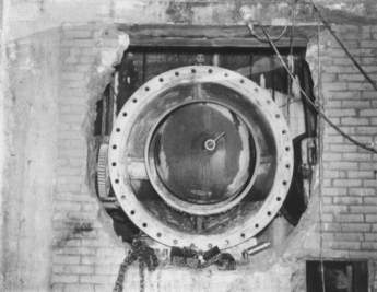
After demolition, the plugging system was lowered to the gate chamber, assembled and installed on the downstream flange of rotary valve No. 2 (photo 9). The plug was inserted through the valves without binding, rubbing or any other dimensional interference. The plug was inflated with nitrogen and there was zero leakage. Initially, we anticipated the plug being installed for a short duration, during disassembly and reassembly. The plug remained installed in each valve for over a month with zero leakage.
With the rotary valves totally drained R.H. White was able to prepare the surface of the valves for a new finish coat of a high performance epoxy coating. The by-pass piping and valve, and the bottom flush valve blind flanges were removed, and the new stainless steel piping and valves were installed.
The seal gland was removed from the valve and the project team had their first look at the existing seal. The seal was constructed of leather, which was no surprise given the age of the valve. The configuration was a ‘hat-leather’ flange seal that utilised a steel contractor ring and the hydrostatic pressure in the stuffing box to maintain the seal. After removal of the existing seal, dimensions of the stuffing box were taken and a new seal was designed by CDM for its replacement.
Unlike modern ball valves that have bodies constructed of four separate castings instead of two, the rotary valve stuffing box was split down the middle. Given the split and rough surface finish on the interior, CDM decided to design a new leather seal in a vee-packing configuration. The seal would consist of three packing rings with cast bronze male and female adapter rings. The design was completed and a change order was issued for the new seal.
The leather seals were fabricated by C.W. Marsh Co. in Muskegon, Michigan. Custom machined dies had to be fabricated to form the vee-packing rings due to the metric dimensions and large shaft diameter. CDM specified a petrolatum impregnated leather for the rings, which would make them softer and more suitable for the surface finish in the stuffing box. The adapter rings were machined from bronze tubular castings in a local machine shop.
After rehabilitation of the rotary valves was complete, the jet flow gate and HPUs were delivered to the site for installation. Hydraulic piping was specified as schedule 80 stainless steel with 3000lb socket welded fittings. The piping was TIG welded on site. By June 2006 the jet flow gates and HPUs were installed and ready for testing (photos 10,11 and 12).
The flow test
In anticipation of the test, SWSC maintained the reservoir level at spillway crest elevation. At the maximum head, the jet-flow gates were expected to discharge a maximum flow at full-open of 300-mgd or 210,000-gpm each. The exit velocity at the jet-flow gate would be approximately 23m/sec. There was a major rainstorm on the designated test day, but this did not deter the test.
The discharge flow from the gates into the tunnel creates an air demand that must be satisfied. This is known as insufflated air and the flow rates can be extremely high. The air demand is caused by the displacement of air by water droplets at high velocity, and the aerodynamic drag caused by them. As the high velocity spray generated by the flow increases, the air demand increases. This demand peaks at approximately 60% of gate stroke, and then drops off as the flow becomes a cylindrical jet and the spray diminishes. This phenomenon also occurred during needle valve operation, which is why the air shaft was constructed above the bell-mouth of the tunnel.
It is nearly impossible to accurately predict the air demand from the jet-flow gates but it was necessary to know the effect it would have on the static air pressure between the gate chamber and bell-mouth chamber, which was separated by a new reinforced masonry wall. The wall was designed for a load of 16-psf, which equates to a differential static pressure of 3”-water-column. If the differential pressure exceeded this value the wall could fall down. The design team considered installing a reinforced concrete wall instead of masonry, but this would limit access to the chamber for future maintenance without the use of heavy demolition equipment. It was better to quantify the differential pressure and provide means for vacuum relief.
A testing procedure was developed by CDM and instrumentation was installed to measure hydraulic and other parameters at various locations around the facility. A digital wind-speed gauge with data logger was installed in the air shaft to measure air demand. A Magnahelic differential pressure gauge was installed between the tunnel bell-mouth and gate chamber to measure differential pressure. A pressure transducer and data logger were installed upstream of the rotary valve on outlet No. 2, and a noise meter was installed in the gate chamber to determine whether hearing protection would be required in the future during operation. The upstream pressure would be used to calculate the flow at different gate positions using data provided from the USBR.
The test was a complete success and was well documented. The maximum flow from both jet-flow gates was recorded at approximately 600-mgd, and the 11’-6” (4m) diameter diversion tunnel was flowing full at the discharge portal, under pressure, at this flow rate. The maximum airflow in the shaft with both gates fully open was 5943m3/min.
The differential pressure between chambers was beyond measure, when both gates were opened simultaneously, and the gate chamber access door closed. The door was opened to allow sufficient air to flow down the access stairwell to relieve the vacuum. There was no vibration from the jet-flow gates during the test and noise levels were below OSHA limits at all times, even when the door was opened. The rotary valves created some periodic, loud cavitation that was clearly audible when the jet-flow gates were fully open, but was not a cause of concern.
In order to minimise risk to the water supply and maintain safe working conditions, the construction schedule was extended by nine months beyond the completion date. The time extension had no major impact on the final cost of the project, which was $1.44M with less than 3% net change orders.
Photo 1: Diversion tunnel under construction Photo 1 Photo 2: Diversion tunnel entrance portal Photo 2 Photo 3: Cobble Mountain diversion gate-house, 1931 Photo 3 Photo 4. Escher Wyss rotary valves shipped from Zurich, Switzerland to the Cobble Mountain site, 1931 Photo 4 Photo 5: View downstream in the diversion tunnel showing rotary valves installed in the gate chamber Photo 5 Photo 6a: Needle valve No. 2, showing internals during mechanical
overhaul (1960’s) Photo 6a Photo 6b: Gate chamber (2002) Photo 6b Photo 7: Closing jammed needle valve Photo 7 Photo 8: Rotary valve worm gear drive showing leaking shaft seal Photo 8 Photo 9: Pluging system installed on rotary valve no 2 Photo 9 Photo 10: Rehabilitated rotary valve w/plug Photo 10 Photo 11: Jet flow gates and rotary valves looking downstream Photo 11 Photo 12: Jet-flow gates and discharge piping looking upstream Photo 12 Figure 1 Figure 1 Figure 2 Figure 2 Figure 3 Figure 3 Figure 4 Figure 4 Figure 5 Figure 5 Figure 6 Figure 6 Figure 7 Figure 7 Figure 8 Figure 8 Author Info:
Neill J Hampton P.E., Project Manager, Camp Dresser & McKee Inc, Wethersfield, CT. Email: hamptonnj@cdm.com; and James Constantino, Sr Water Supply Supervisor, Springfield Water & Sewer Commission, Springfield, MA. Email: jim.constantion@waterandsewer.org.