A new way to measure reactor temperatures up to 1000 °C is proposed, based on the comparison of acoustic signals in gas-filled tubes. Proof-of-concept experiments demonstrate an accuracy of within 2 °C with just one calibration point, although drift remains a potential issue. By Michael de Podesta

Temperature measurement is important to a greater or lesser extent in any engineering endeavour. In a power station using steam turbines to generate electricity, accurate temperature measurement is critical in optimising plant operation. In a nuclear power station measurement of temperature is just as critical, but in irradiated areas the measurement is complicated by the fact that all conventional temperature sensors mis-read substantially when exposed to radiation. It would be a considerable benefit to have a thermometer that could be relied upon to read correctly even after millions of grays of irradiation.
In this article I will describe a Practical Acoustic Thermometer (PAT) which could potentially fulfil this task.
Guided sound as a thermometer
The concept of ‘speaking tubes’ in the noisy environment of a steam engine was realised early on in the industrial revolution. Examples can be seen for example in the engine room of the SS Great Britain built in 1843. In a speaking tube, horns couple sound into and out of a tube of approximately 2.5 cm diameter. The tube could be tens of metres long and provided only that it was bent smoothly around corners, the sound was guided along the tube with low loss (Figure 1a).
It was not until 1872 that Mayer realised that the phenomenon of guided sound could be exploited to measure temperature and demonstrated a device consisting of coils of copper tube held in a furnace [1]. Using an organ pipe, resonances were excited in air inside a 13 metre-long tube and the resonance was detected by the flickering of a flame held close to the end of the tube. Although fascinating in retrospect, the technology was cumbersome, and the idea was quickly forgotten as the world discovered and fell in love with thermocouples.
The idea has been resurrected a couple of times in the United States [2] and Germany [3, 4] and has been suggested as a solution for nuclear engineering problems. However it does not appear to have been adopted widely, if at all.
Background: impractical acoustic thermometry
This is where things stood in 2007 when the National Physical Laboratory began work on a project to build the most accurate thermometer in the world [5, 6]. The heart of the thermometer is an exquisitely-crafted spherical resonator through which we gently flow ultra-pure argon gas. By measuring the frequencies of acoustic resonances in this cavity it is possible work out the speed of sound c in the argon gas directly, if the size of the resonator is known. By measuring at a number of pressures we can extrapolate to find the speed of sound in the limit of low pressure c0. We can then calculate the absolute temperature T using the simple Equation 1:
![]()
where R is the molar gas constant, M is the molar mass of argon, and gamma is the adiabatic index of the gas which is exactly 5/3 for a monatomic gas. The resonator approach allows the speed of sound to be measured with uncertainties below one part in 107. Because Equation 1 is exactly correct — despite many additional complexities — it allows us to measure temperatures with an uncertainty of less than 0.001 °C.
The quest for a practical acoustic thermometer
The resonator thermometer is impractical for general use: its purpose is to detect the errors in other thermometers and allow for their correction. But as we built the apparatus and pondered the simplicity of Equation 1, we wondered whether there was a way to make a practical thermometer that could have an uncertainty of measurement 1000 times larger, that is, 1 °C, but which could still be useful. It was at this point that we ‘re-invented’ the guided-wave-in-a-tube concept of Mayer.
The re-invention was not made out of idle whimsy: a practical acoustic thermometer (PAT) would have three desirable features. Firstly it would be based on well-understood physics and would be intrinsically simple and cheap to build; it’s just a tube with some acoustic transducers. Secondly, it could potentially have a very high upper measurement limit: if the tube survives and the gas does not ionise, then the thermometer should still function. And finally the thermometer would be as robust as the tube from which it was made — which could be metal, ceramic or plastic — depending on the range of application. From a nuclear perspective, this meant that a PAT device built from suitable materials could be potentially free from radiation-induced drift. These potential advantages convinced us that the goal of building a practical acoustic thermometer was a worthwhile challenge.
Initially my colleague Gavin Sutton and I would spend occasional Friday afternoons ‘pinging’ sound along tubes and measuring delay times. Then with the free labour of some school students we constructed a crude device with which we measured temperatures up to 1000 °C. Based on a single calibration at 200 °C, the error at 1000 °C was 40 °C [7]. However if we had calibrated the thermometer at more than one point, it would have been straightforward to deduce an uncertainty of measurement of approximately ±2 °C. This experiment had been so simple to perform that we were convinced that a practical device must be possible.
One feature of the work which seemed at first to be merely incidental turned out to be central to the measurement problem: the acoustic pulse shape. The shape of the acoustic pulse was problematic for two reasons. Firstly sending a perfect electric pulse of 1 ms duration to a loudspeaker does not result in a perfect acoustical pulse of 1 ms duration. Instead the loudspeaker rings, giving an acoustic pulse with a tail of oscillations lasting many milliseconds. And secondly, the pulse shape changes as it travels along the tube (Figure 2).
The key to accurate results
The key to accurate results lies in avoiding loud pulses which drive the loudspeaker into a non-linear regime, and instead using quieter and longer acoustic ‘chirps’. We then use a complex analysis to measure how each frequency component within the chirp travels along the waveguide. Although in free space all acoustic frequencies travel with very low loss, in a waveguide, sound is affected by thermal and viscous processes in a boundary layer at the wall of the waveguide. The effect of this layer is to cause the speed of sound in the waveguide, v, to differ from the free-field speed of sound, c, with lower frequencies being more affected than higher frequencies. However, higher frequencies are more strongly absorbed than lower frequencies. There is thus an optimal range of frequencies — typically in the range 1 kHz to 5 kHz — for which sound travels with low loss along the waveguide, but for which the speed of sound is close to (typically within 5% of) the free-field value. It was these frequency-dependent variations in absorption and speed which caused our pulses to change shape. By measuring the ‘transfer function’ for each frequency we are effectively exploiting the phenomenon which gave rise to the original problem of changing pulse shape.
Experimentally we send a range of frequencies along the waveguide as a ‘chirp’. Each frequency within the chirp propagates with its own speed and absorption. By comparing the ‘as received’ chirp with the ‘as transmitted’ chirp we can calculate how each frequency within the chirp has propagated. This can be compared with the theoretical way we expect the sound to propagate along a length of tube, including the effect of reflections and resonances.
Adopting this procedure we made great advances in our understanding, but this was still not enough to make an accurate thermometer. The reason why is that this procedure works out the average temperature along the entire length of the waveguide. However, typically we are interested in the temperature in a specific region of the waveguide. In order to achieve this we use two waveguides of different lengths. These can be configured in a variety of ways (Figure 3) and we evaluate the difference in transit times between the two waveguides. In this way we can determine the local temperature in a region of a waveguide.
Acoustic thermometry: experimental results
Since the breakthrough in our understanding, we have constructed several thermometers that have shown exceptional performance both at high temperatures and at around room temperature. But in order to ensure reproducible measurements it is essential that the waveguide remains dimensionally stable, and that the gas within the waveguide remains pure and at approximately the same pressure.
The requirement for dimensional stability of the waveguide is easy to appreciate: this is a timing measurement and if the material from which the waveguide is constructed creeps or undergoes crystallographic changes, then the length of the waveguide may change. It will then take more or less (but usually more) time to travel from speaker to microphone and our inference of the speed and hence the temperature will be in error. Thus the choice of material is dictated by the requirement for dimensional stability after multiple temperature cycles, and metals, ceramics and plastics are all appropriate in different temperature ranges. For nuclear applications the choice of materials is obviously restricted, but dimensionally-stable engineering materials are available.
Gas purity is essential in order to minimise corrosion at high temperatures which in turn affects dimensional stability, and also — and more fundamentally — to maintain the correct inference of temperature from a particular measurement of speed of sound. Purity can be achieved by first heat-treating the tube to minimise out-gassing and then hermetically sealing the gas inside. The heat treatment can include deposition of silica-like surface coatings. Alternatively, in our experiments we instead maintained a constant gas flow (50 standard cubic centimetres per minute) through the device. This is a practical alternative in many industrial plant settings and its small effect on the speed of sound is corrected by ‘chirping’ sound both ways along the tube.
Inconel 600 device
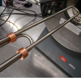
Our first high-temperature devices (Figure 4) were made from Inconel 600 to a standard design, approximately 1 metre long with a sensitive length of approximately 20 cm. We chose this design with a long ‘non-measuring’ length to test the ability of the reference tube to compensate for changes in external temperature. We placed the device in a tube furnace and compared the PAT device with a calibrated Type R thermocouple.
First results were promising. Figure 5 shows the difference between the temperature inferred from the PAT device, TPAT and the thermocouple reading, TTC for a device made from Inconel 600. The device is calibrated at 20 °C by adjusting the nominal length of the transit zone until TPAT agreed with TTC. This is the only calibration point: all other temperatures are inferred from measurements of the tube dimensions, the known thermo-physical properties of argon gas, and an estimate for the thermal expansivity of the Inconel 600. At 1000 °C TPAT exceeds TTC by approximately 12 °C. This error most probably arises from mis-estimation of the thermal expansivity of Inconel 600. However, the error can be corrected by calibration at the upper temperature and a quadratic curve fit yields an inferred temperature within ±1 °C at all temperatures up to 1000 °C.
Silica device
To check our understanding we then constructed a similar device made of silica. This was a rather delicate instrument, but the exceptionally low thermal expansivity of silica (0.48 ×10⁻⁶ °C-1) meant that poor knowledge of the expansivity was unlikely to cause a significant error: the results (Figure 6) matched our expectation. Based on just a single calibration at 50°C differences between TPAT and TTC were less than ±2 °C at all temperatures up to 1000 °C. This indicates that we must have understood the key physics required to make these devices work.
One of the hoped-for advantages of the PAT technique is that the thermometer should not drift, so one of the main goals of our research was to see if this was really true. We carried out tests on the Inconel 600 device by cycling from 400 °C to 700 °C to 1000 °C, with a four-hour dwell at each temperature. It quickly became apparent that the devices drifted (Figure 7). After 50 days exposure to this regime, the indication at 1000 °C had fallen by 6 °C. We are still trying to understand precisely why this happened but examination of the Inconel after exposure revealed a greenish coloration indicative of the presence of chromium oxide. It thus seems likely that chromium from the Inconel had migrated to the surface, and this could easily have resulted in changes in the tube diameter and length. At the moment we think the drift at 700 °C and 400 °C largely reflect dimensional changes which occurred in the alloy at high temperatures. We are currently conducting more careful soak tests to establish the upper limits of dimensional stability of the Inconel 600 device.
Development prospects for acoustic thermometers
PAT technology represents the application of acoustic engineering gained in the most rarefied of research environments to some of the most difficult temperature measurement problems in industry. We have established that PAT technology does work in practice and we believe it could potentially be useful in a variety of applications, many of them in the nuclear field. However in order to make any PAT technology truly practical, we need partners with whom we could work to develop products that can be used in the real world.
If you have a facility (radioactive or not) in which you would be prepared to let NPL scientists install devices, or you would like to partner with the National Physical Laboratory to create marketable products, we would love to hear from you.
About the author
Michael de Podesta is Principal Research Scientist, National Physical Laboratory, Teddington, Middlesex TW11 0LW
This research is funded by the Department for Business, Innovation and Skills as part of their support of the National Measurement System. Some parts of this research have also been funded under the NOTED and Metrofission projects of the EMRP (European Metrology Research Programme) which is jointly funded by the EMRP participating countries within EURAMET and the European Union.
References
1. A. M. Mayer, ‘On an Acoustic Thermometer,’ Phil. Mag. Vol XLV (1873) page 18.
2. J. H. Apfel, ‘Acoustic Thermometry’, Review of Scientific Instruments, 33(4) 1962.
3. H. Ziegler and M. Spieker, Proceedings of Tempmeko 1996, Editor P Marcarino, pp. 451-456.
4. Hans-Jurgen Aulfes, Akustisches Gasthermometer mit dünnen Sensorrohren, PhD Dissertation, University of Paderborn, 1993.
5. ‘A low-uncertainty measurement of the Boltzmann constant’ M de Podesta, R Underwood,
G Sutton, P Morantz, P Harris, D F Mark, F M Stuart, G Vargha and G Machin, (2013) Metrologia 50 354 doi:10.1088/0026-1394/50/4/354.
6. Physics World, "Redefining Temperature" August 2013.
7. M. de Podesta, G. Sutton, R. Underwood, S Legg, A Steinitz, Int J Thermophysics (2010) 31:1554-1566.