Empirical formulae have been developed for estimating the weight of steel in a hydro powerhouse superstructure containing vertical axis turbines. By J L Gordon
Calculating the weight of steel required in a powerhouse superstructure is a time-consuming task, but necessary for costing developments. By reviewing the statistics for 12 hydro plants, containing vertical shaft reaction turbines, where the weight of the superstructure steel was known, it was possible to develop a formula for the weight based on the turbine runner throat diameter, number of units, repair bay length ratio and capacity of the powerhouse crane.
For reaction units, it was reasoned that the superstructure weight should be a function of the crane capacity and the cube of the runner throat diameter. The latter parameter was selected as being representative of the powerhouse superstructure volume, since the unit bay area is a function of the runner diameter squared, and the height of the powerhouse superstructure is approximately related to the runner diameter. To arrive at a comparative weight for the superstructure, the weight per bay was determined by dividing the total superstructure weight in tons by the number of units plus the repair bay ratio. The repair bay ratio is defined as the length of the repair bay divided by the unit spacing. The definitions of the terms used are as follows:
• C = Crane capacity in tons.
• d = Runner throat diameter in meters.
• h = Turbine rated head in meters.
• n = Number of units in powerhouse.
• N = Synchronous speed of runner, rpm.
• R = Repair bay ratio.
• W = weight of superstructure steel in tons.
The 12 hydro plants have runner diameters ranging from 1m to over 7m, and crane capacities ranging from 20 tons to over 200 tons, as shown in Table 1. For single units, the repair bay ratio was determined by using a nominal unit spacing based on 3.6 times runner diameter, plus 1.6m, a formula obtained from reference 1 (Gordon, 1982), which was developed from an analysis of 20 power plants. Two power plants – at Whitehorse and Kainji – have no repair bays. Both are extensions of existing power plants, so additional repair bay space was not required.
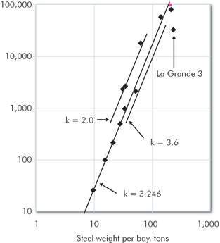
The weight per bay was then plotted on a logarithmic scale against the parameter Cd3 as shown in Figure 1.

Figure 1: Relationship between steel weight per bay and crane capacity (C) times runner diameter (d) cubed
From Figure 1, a formula for superstructure steel weight was developed as follows:
(1) W (reaction units) = k (n + R) C0.358 d1.074
Where k = coefficient with a value which varies from a minimum of 2.0 to a maximum of 3.6, with a mean value of 3.25, as shown in Figure 1. One power plant at La Grande 3 has a superstructure weight higher than calculated. This is due to locating the switchyard on the powerhouse roof, requiring a considerably more robust structure.
For impulse units, there was only data from one powerhouse at Cat Arm, insufficient to derive a formula using the same methodology. Hence it was decided to assume that an impulse formula would have the same form as that for reaction units, with the diameter representing the impulse runner outer diameter. Impulse data was based on reference 2, (Mosonyi, 1965). At Cat Arm, the powerhouse crane has a capacity of 135 tons and the repair bay factor is 1.00. There are two units, with the outer diameter of the Pelton runner measuring 3.00m. The rated head is 386.3m, the synchronous speed is 327.3rpm, and the weight of superstructure steel is 450 tons. Substituting these numbers in Formula 1, produces the following:
(2) W (impulse units) = 7.96 (n + R) C0.358 d1.074
The diameter of impulse units is a function of the square root of the head divided by the runner speed (2), hence an alternative formula could be devised from the Cat Arm data as:
(3) W (impulse units) = k (n + R) C0.358 (h0.5/N)1.074
With the value for k being determined from the Cat Arm data as:
(4) W (impulse units) = 531 (n + R) C0.358 h0.537 N-1.074
In Formula 2, the coefficient 7.96 appears to be reasonable, since the spacing between vertical axis impulse units is about six times the outer runner diameter, to allow for the much larger impulse unit distributor footprint, as compared to the footprint of a reaction unit spiral casing. If it is assumed that impulse power plant superstructure steel weights are proportional to those for reaction units, based on the relative powerhouse footprints, then the coefficient of 3.246 in Formula 1 could be increased by 3.246 x 62/3.82 = 8.09, to arrive at a value very close to the value derived in Formula 2.
Finally, the Cat Arm powerhouse includes space for SF6 switchgear. During design of the superstructure, the space allowed for the switchgear became too large, as the volume of the switchgear reduced remarkably due to advances in the technology. Unfortunately, it was too late to re-design the superstructure steel. The effect of a smaller switchgear room on the superstructure steel weight has been estimated at a reduction in the coefficient in Formula 4 to a value of about 450.
Conclusions
The formulae developed in this paper will greatly simplify the costing of powerhouse superstructures in pre-feasibility assessment of hydro developments, and should prove to be valuable in computer programs designed to assist such assessments.
Jim Gordon is an independent hydro consultant and can be reached at 102 Blvd. St-Jean, Pointe Claire, Quebec, Canada, H9S 4Z1. Email: jim-gordon@sympatico.ca
TablesTable 1