Ontario Power Generation’s Niagara tunnel project includes the planning, design and construction of a 10.2km long, 12.7m internal diameter tunnel and associated facilities to divert an additional 500m3/sec of water from the Niagara river upstream from the Horseshoe Falls to the existing Sir Adam Beck generating stations near Queenston. The design/build contractor, Strabag, is using the world’s largest hardrock tunnel boring machine to excavate the tunnel. By Richard A Everdell
There is over a century of hydroelectric development experience on both sides of the Niagara river. The first plants were built adjacent to the falls, used only the hydraulic head in the vicinity of the falls and all generated at a frequency of 25Hz. The Canadian Niagara Power Company (CNP), the Toronto Power Company (TP) and the Ontario Power Company (OP) stations were built on the Canadian side while the Adams and Schoellkopf stations were on the US side. The plants on the Canadian side were built by private companies between 1900-10. The OP and TP facilities were purchased in about 1920 by the Hydro-Electric Power Commission of Ontario which, in 1974, was renamed Ontario Hydro, the immediate predecessor of Ontario Power Generation (OPG).
Sir Adam Beck GS No.1 (SAB1), built in the early-1920s, is OPG’s third largest hydroelectric station with ten units having a total installed capacity of 498MW. It was the first of the Niagara river hydroelectric facilities to capture the hydraulic head available through the rapids upstream and downstream from the falls, facilitating capture of 95% of the drop between Lake Erie and Lake Ontario. A 20km long open-cut canal was constructed between Chippawa and Queenston to deliver about 600m3/sec of Niagara river water for hydroelectric generation at SAB1. Originally, the SAB1 units all generated 25Hz electricity, but since Ontario’s 60Hz standardisation in the 1950s, eight generators have been converted from 25Hz to 60Hz. Two SAB1 units continue to supply 25Hz electricity to a few customers.
Sir Adam Beck GS No.2 (SAB2) is OPG’s largest hydro station with 16 units having a total installed capacity of 1499MW. SAB2 is the flagship of OPG’s hydro fleet. It was constructed in the early 1950s and first operated in 1954. Two 13.7m diameter, 8km long diversion tunnels joined into a 3km long open-cut canal to deliver about 1200m3/sec of Niagara river water for hydroelectric generation.
During a major overhaul and upgrade of SAB2 between 1996 and 2005, the turbines, generators and other primary equipment were replaced, renewing the station’s reliability and increasing its capacity by 194MW.
The Sir Adam Beck Pump Generating Station (PGS) and reservoir were also built in the 1950s, first operating in 1958. The PGS has six reversible units with a combined nominal capacity of 174MW. The PGS reservoir is a manmade lake, contained by a rockfill dyke that rises above the natural terrain. The PGS reservoir is operated over a range of 8.2m and has a storage capacity of about 20Mm3. Water is typically pumped into the PGS reservoir from the SAB canals during periods of low electricity demand (over night and on weekends) and released to generate electricity at the PGS and at SAB1/SAB2 during periods of peak demand.
Combined, the Sir Adam Beck – Niagara generating stations provide 30% of OPG’s hydroelectric capacity and 35% of OPG’s clean, renewable hydroelectric energy.
In 1956, the Schoellkopf plant was destroyed by a catastrophic failure of the rock cliff which caused part of the plant to be pushed into the Niagara river. In the early 1960s, NYPA built the 2400MW Robert Moses generating station, and its companion 300MW Lewiston pump generating station, on the lower Niagara river opposite the SAB plants. This allowed the US to use a larger portion of the available water and the less efficient Adams and Schoellkopf plants were removed from service.
Progressively, the TP, OP and CNP plants on the Canadian side of the river were also closed as 25Hz demand dwindled. OPG’s remaining hydroelectric facilities at the Sir Adam Beck complex did not have enough diversion capacity to fully utilise Canada’s allocation of Niagara River flow under the terms of the 1950 Treaty.
The Niagara tunnel project, now under construction, will restore Ontario’s capability to effectively utilise the water allocated to Canada. When the new Niagara tunnel is in operation, the water it delivers will permit the existing Sir Adam Beck generating stations to produce 14% more energy, increasing average annual output by about 1.6BkWh, enough to supply 160,000 Ontario homes with clean, renewable hydroelectric power.
Deciding to build the tunnel
Preparation for the new Niagara tunnel commenced in 1982, when Ontario Hydro (predecessor of OPG) began to study the possible expansion of its hydroelectric facilities on the Niagara river. Detailed engineering, environmental and socioeconomic studies were conducted from 1988 through 1994 with an environmental assessment (EA) submitted in 1991 for the then planned project (two 500m3/sec water diversion tunnels, a 3x900MW underground generating station and transmission improvements between Niagara Falls and Hamilton, Ontario).
Among the commitments made through the EA process was the utilization of a tunnel boring machine (TBM) to excavate the tunnels from the outlet end, under the buried St. Davids gorge and following the route of the existing SAB2 tunnels through the City of Niagara Falls. Other commitments included re-use of excavated materials and an agreement to compensate the host municipalities, Niagara Region, Niagara Falls and Niagara-on-the-Lake, for forecast project impacts on tourism and municipal services. The EA received approval from Ontario’s Minister of the Environment in 1998, including provisions to begin with construction of one tunnel, the Niagara tunnel project.
The project team
Due to their expertise in tunnel design and construction, prior work on the project and knowledge of the area, OPG engaged Hatch Mott MacDonald (Mississauga) in association with Hatch Acres (Niagara Falls) as the owner’s representative to assist with administration of the design-build contract, to review design documentation and to monitor construction.
Through an international proposal competition, OPG contracted with strabag to design and construct the Niagara tunnel. Headquartered in Vienna, Austria, Strabag has extensive international tunnelling experience, having built many of Europe’s railway and highway tunnels. Strabag’s project team includes ILF (Austria) as tunnel engineer, Morrison Hershfield (Toronto) as surface works engineer, Isherwood (Mississauga) as cofferdam engineer, and several local specialty subcontractors including Dufferin Construction (Oakville) for surface works and excavated materials handling, Castonguay (Sudbury) for blasting, McNally and Bermingham (Hamilton) for in-water works, Geofoundations (Acton) for grouting, Dufferin Concrete (Toronto) for shotcrete and concrete supply, and Jegel (Toronto) for quality control.
Geological setting and challenges
The Niagara region is underlain by Cambrian, Ordovician and Silurian sedimentary rocks having a total thickness of approximately 800-900m (see Figure 1). The formations feature near horizontal bedding that dips at 2m/km from east to west. The strata include dolostones, dolomitic limestones, sandstones, and shales.
The Niagara river gorge was formed by erosion during the last major ice retreat, about 12,000 years ago. Then, the Niagara river ran through the St. Davids gorge, but roughly 10,000 years ago its route changed to the current alignment. The falls eroded and retreated at a rate of approximately 1m per year to where they are today, with retreat now slowed by counter measures and the diversion of about two-thirds of the flow for power generation.
Geotechnical investigations were carried out in stages and included 58 boreholes, in-situ stress measurements, groundwater monitoring wells and an exploratory adit. Concept phase investigations for potential development schemes were carried out by Ontario Hydro from 1983-89. Definition engineering studies were carried out from 1990-93. Investigations in 1992-3 included the excavation of an adit with a 12m diameter trial enlargement in the Queenston formation about 1km from the tunnel outlet.
In the various formations above the Queenston shale mudstone, the unconfined compressive strength ranges from 12-242MPa while the tensile strength ranges from 6-9MPa. In the Queenston formation, the unconfined compressive strength ranges from 7-120MPa and the tensile strength ranges from less than 1-14MPa.
Host rock challenges for tunnelling activities include:
• High in-situ ‘locked in’ horizontal stress three to five times the vertical stress.
• Shale degradation when exposed to air.
• A groundwater regime including very permeable aquifers in the upper units, highly corrosive groundwater below the DeCew formation, a regional acquitard provided by the Rochester shale and very low permeability but highly corrosive connate pore water in the Queenston formation.
• Natural gases (methane) detected in various formations.
• Time-dependent deformations including squeezing into excavations due to relief of high stresses. Swelling potential of the shale units is well documented in the Niagara region. It is believed to be initiated by the relief of the high in-situ stresses, shales that ‘swell’ in fresh water or humidity and due to ionic diffusion of salts from the connate pore water.
Tunnel design
The planned tunnel alignment sees the tunnel descend 1400m on a 7.82% decline from the outlet through the upper sedimentary layers and into the Queenston shale formation to a depth of 140m below the ground surface. From there, the tunnel was planned to follow a relatively flat plane for about 7800m before rising towards the intake on a 7.28% incline for the final 1200m. All horizontal and vertical curves have a radius of 1000m and there are no compound curves.
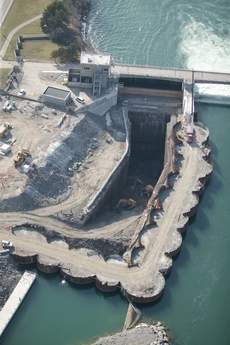
The significant challenges of safely excavating and supporting the Queenston shale have resulted in rerouting part of the tunnel, rising to the underside of the Whirlpool sandstone formation, about 100m below the ground surface, starting about 3300m along the tunnel drive (see Figure 2). To facilitate the vertical realignment, the horizontal alignment was shifted about 200m east, directly below Stanley Avenue and out from the shadow of the existing SAB2 tunnels (see Photo 1). This shortened the tunnel length by about 200m to 10.2km.
The clay minerals in the Queenston formation expand and absorb water, resulting in rock swelling that could potentially put the tunnel lining under a great deal of stress. The rock swelling was studied in detail during the project’s definition phase. Strabag’s design features a two-pass approach developed to ensure the tunnel is protected from swelling rock.
As the tunnel is being bored, workers behind the TBM cutterhead install various combinations of steel ribs, wire mesh, and rock bolts to reinforce the rock. The surrounding surface is then sprayed with a layer of shotcrete to cover the exposed rock and form a protective shell. The tunnel is subsequently lined with a polyolefin waterproofing membrane that prevents fresh water in the tunnel from entering the host rock and eliminates the swelling potential. The final liner consists of cast-in-place concrete 600mm thick.
The tunnel is being driven by a Robbins (Solon, Ohio, US) full face, open gripper TBM with an outside diameter of 14.44m. It is the largest in the world of this type. The tunnel design inside diameter varies between 12.4-13m depending on the primary support class dictated by the host rock conditions.
The smaller diameter reflects the less frequently expected case where steel ribs and mesh would be required with up to 100mm of 25MPa shotcrete. The other primary support classes vary from mesh with 50mm of shotcrete, to steel channels with mesh and rockbolts up to 6m in length, and 80mm of 25MPa shotcrete.
The final lining incorporates a polyolefin waterproofing membrane to prevent swelling of the host rock, a 120 degree cast-in-situ concrete invert, a 240 degree cast-in-situ concrete arch, contact grouting to fill voids and interface grouting to pre-stress the liner against the internal pressure during operation. The waterproof membrane is installed between the shotcrete sprayed onto the exposed rock surface and the final concrete lining. It is essential to the design life and quality of the tunnel lining because it prevents fresh water flowing through the tunnel from leaking into the surrounding rock and displacing the supersaturated salt water trapped in the rock. If this were to occur, the rock around the tunnel, in particular the Queenston shale, would swell and over-stress the concrete lining.
Use of this type of waterproof membrane is rare in North America, but it is used in many railway and highway tunnels in Europe. An added benefit of the membrane is that the concrete used to build the final liner can be thinner and does not require reinforcing steel. The concrete lining thickness has been optimised based on structural requirements and placement constraints.
Constructing the tunnel
The tunnel excavation is being done by the ‘Big Becky’ TBM and her supporting cast of construction workers. Measuring 150m long, more than four storeys tall and weighing about 4000 metric tonnes, Big Becky was named through a contest involving students from across the Niagara region. The winning submission came from children at Port Weller Public School in St. Catharines, Ontario. The children say they chose the name in honor of Sir Adam Beck, the man who presided over the building of the original SAB1 generating station.
Big Becky was designed, manufactured and built in less than 12 months. She was assembled in the 300m long, 23m wide, 30m deep rock cut outlet canal using custom parts shipped from Germany, Hungary, Italy, Slovenia, the UK, the US and Canada (see Photo 2).
Big Becky is digging under the City of Niagara Falls from the Sir Adam Beck generating complex, near Queenston, to the international Niagara control works located about 1.5km upstream from the Horseshoe Falls. The control works extends about half way across the Niagara river to regulate the flow of water over the falls in accordance with the 1950 Treaty and also facilitates ice management in the vicinity of the hydro power diversion intakes.
Big Becky’s cutterhead is dressed with 85 x 508mm cutters and is powered by 15 x 315kW variable frequency electric motors to carve through the 450M-year-old rock that underlies Niagara Falls. Big Becky progresses through the tunnel by first using hydraulic pistons to push heavy steel gripper pads against the tunnel sides for support. The cutterhead, rotating at up to 5rpm, then bores through about 1.8m of solid rock as hydraulic thrust cylinders push the cutterhead forward. The grippers are retracted after the rear legs are lowered for support, and the backup trailers are pulled forward with another set of hydraulic cylinders to catch up with the front of the TBM in a caterpillar-like motion.
Concurrently, the trailing series of 1600t/hr conveyor belts carry the excavated rock out of the tunnel to a storage area located on OPG property at the Sir Adam Beck generating complex. The excavated Queenston shale will become feedstock for Ontario’s clay brick industry, while excavated limestones from the intake and outlet excavations were recovered for on-site uses and nearby public works projects.
Big Becky began her underground journey in September 2006. It will take several years to complete the tunnel drive. By the time Big Becky arrives at the tunnel intake, she will have bored through 1.7Mm3 of solid rock.
Compared to the 10,000 workers needed to build SAB1, the new Niagara tunnel is being constructed with an average of only 230 workers, rising to about 350 workers during periods of peak activity. This unionised job site features a predominately Canadian workforce working on a 24/7 cycle with two production shifts at 10 hours each, plus one maintenance shift. Despite the challenging conditions and on-site effort to date exceeding 2.2M hours, the crews and site management team have achieved a commendable lost time injury frequency rate below 1.0 per 200,000 hours worked, which compares favourably to the Ontario heavy civil construction industry rate of 2.9.
One of the challenges faced by the site team is the running of services and logistics through the various work platforms as the placement of the cast-in-place concrete liner is carried out concurrent with TBM excavation. Up to four concurrent activities could be staged along the tunnel route before hole-through of the TBM.
Lining station
Launched in December 2008, and trailing behind the TBM by about 3000m, is the 800t invert lining work station (see Photo 3). It was engineered and fabricated by Strabag group companies BMTI and Baystag. An 87m long bridge section, ramped at both ends, allows the rubber tired tunnel supply vehicles to travel uninterrupted in a single lane as the polyolefin membrane is installed and the invert concrete is cast. The crown and sidewall bracings on the invert formwork, necessary to prevent heave, have been designed so as not to interfere with the 2.6m diameter fresh air supply duct. This runs along the tunnel crown or the sidewall mounted conveyor and opposing electrical, communication and water services. The invert is being cast using two 12.5m long forms that can be leapfrogged to facilitate 25m of invert lining advance per day.
Excessive overbreak in the tunnel crown, particularly in the Queenston shale formation (see Photo 4), has necessitated addition of the 100t infill carrier to restore the profile prior to installing the membrane and arch concrete. It will follow the invert lining by about 1500m and is currently planned for launch in September 2009. It will provide elevated work platforms to accommodate drill jumbos, grouting facilities, shotcrete robots and material handling equipment needed for the arch profile restoration.
Trailing the infill carrier by another 1500m will be the twin 12.5m arch forms and associated membrane installation platform configured like the invert lining work station to facilitate daily advance of up to 25m. The arch installation carrier weighs in at a hefty 1800t and totals about 450m in length. The heavyweight steel is required in the design to resist the concrete loads. The membrane will be installed using Velcro to hold it in place and all seams will be heat welded and fully tested. Tubes with ports for pressure grouting will be installed every 3m along the tunnel lining to facilitate the subsequent grouting operations. The arch lining train will carry services and ventilation, together with the conveyor, on fasteners that are part of its superstructure to channel them through the work area as the membrane and arch concrete are placed.
A further 2000m behind the arch concrete operation will be the 60t contact grouting station. The 60t pre-stress grouting work platform will follow by another 1500m to complete the tunnel’s permanent lining.
Ventilation is presently by means of two 355kW fans for an air supply to the TBM of 75m3/sec. A 75kW secondary fan is installed on the TBM back-up. Once the arch lining is underway, a further 75m3/sec will be delivered to the shutter area to dissipate heat generated during the curing process.
To supply shotcrete and concrete to the tunnel, a batch plant was built just outside the tunnel’s entrance along with a water treatment plant that is used to clarify water pumped from the tunnel before it is discharged to the nearby hydro canal.
Intake works
Overshadowed by the presence of Big Becky, work at the currently separate intake site is an impressive project in its own right (see Photos 5 an 6). Located at the gates of the International Niagara Control Works, in-water blasting was used and precast concrete bins were stacked, backfilled and capped to form the replacement ice-management Accelerating Wall and shoreline retaining wall. A sheet pile cellular cofferdam has been constructed in the river and was dewatered in July 2007. Blasting and rock excavation of the approach channel then got underway, together with grouting works to seal the two main sources of inflow, leaks through the cofferdam and through horizontal layering in the riverbed. The impressive portal profile was achieved by controlled blasting, with scaling / profiling by excavator mounted roadheader.
The 400m long, 8m wide and 7m high grout tunnel, now under construction below the Niagara River bed (see Photo 7), is to precondition and seal the ground in preparation for the TBM breakthrough and to facilitate the demobilisation of the TBM once the main tunnel drive is complete. Extensive grouting is being carried out as the tunnel advances to prepare the ground so that the TBM can drive along the grout tunnel alignment, without experiencing problematic inflows, with the top of the TBM cutterhead just below the crown of the grout tunnel.
Current status
Excavating from the outlet, with the TBM launched in September 2006, the tunnel has been driven downward at a 7.82% grade that has taken the tunnel through ten layers of shale, limestone and dolomite. After breaking through the Whirlpool sandstone, a hard abrasive rock, Big Becky encountered the much weaker Queenston formation. Progress through the contact zone between these two rock formations was difficult, and significant modifications to the initial support area, immediately behind the TBM cutterhead, were completed to enhance the installation of initial rock support and worker safety, a top priority on the project.
In the Queenston shale immediately below the Whirlpool sandstone contact and under the buried St. Davids gorge, Strabag installed a series of 9m long horizontal pipe spile umbrellas to pre-support the rock in the tunnel crown over Big Becky’s cutterhead. This temporarily slowed the progress of the TBM to less than 3m per day. As rock conditions improved, the spile umbrellas were discontinued and the TBM advance rate increased. Crown overbreak in the Queenston shale formation, up to 4m, and averaging about 1.5m, has been experienced with crews now averaging about 7m per day of TBM advance under such conditions.
By mid-April 2009, the TBM had advanced over 3900m and the invert concrete liner installation has advanced about 200m. The progress of the tunnel boring machine has been slower than expected and considerable uncertainty remains with respect to the schedule until the tunnel boring machine establishes more consistent performance following the revised alignment.
Negotiations are currently in progress to re-establish the completion schedule and contract cost consistent with the recommendations of the Dispute Review Board concerning alleged differing subsurface conditions in the Queenston shale formation. As well as with associated excessive crown overbreak, due to challenges experienced excavating and supporting the apparently overstressed Queenston shale in the tunnel crown. The ongoing negotiations are also including contract changes associated with re-routing of the tunnel into the more competent rock formations overlying the Queenston shale.
After Big Becky finishes her job, it will take another two years to complete the installation of the permanent concrete lining and the permanent structures required at the tunnel intake and outlet. The new tunnel is expected to operate for at least 90 years without any interruptions for maintenance.
Rick Everdell is the project director of the Niagara tunnel project. He may be contacted at Ontario Power Generation, 700 University Ave, H18, Toronto, Ontario M5G 1X6 Canada. Email: rick.everdell@opg.com
TablesTable 1