PT Vale Indonesia Tbk operates a mining and nickel-smelting operation on the Indonesian island of Sulawesi. The nickel-processing plant is largely powered by hydroelectric generating stations on the Larona River. When the company decided to increase nickel production in 2003, SNC-Lavalin was invited to enter a design competition for a new hydroelectric facility to increase their generation capacity. The successful design benefitted from two interesting features highlighted in this paper: a distinctive hydro-combine powerhouse arrangement; and a unique failsafe spillway arrangement.
Karebbe generating station (Figure 1) was constructed in the Larona River gorge near the village of Karebbe in Indonesia. It has a 73m high concrete gravity dam, a 130MW powerhouse and a 7km extension of the PT Vale 150 kV electrical transmission system that supplies power to the nickel processing plant and to the national electricity board for distribution in the towns of the local region.
The plan layout of the facility is shown in Figure 2. Karebbe dam was built to pass the Probable Maximum Flood and to survive the Maximum Credible Earthquake. In addition, extensive flood inundation studies and dam break studies were carried out for emergency planning purposes. An independent Karebbe Advisory Board was established and met every three to four months for the duration of the project to review both design and construction. The Dam Safety Commission of Indonesia provided additional independent review and permitting for each stage of the project.
The dam is a concrete gravity structure founded on well-jointed peridotite rock, except for the left abutment, where the foundation is a massive conglomerate rock. There were some springs on the right bank at the dam site and some of the investigation boreholes in the peridotite experienced high water takes. When the overburden was stripped from the dam foundation, several continuous shear zones were found and mapped. The orientation of these zones was favourable in terms of foundation stability, but they were feeding springs and therefore had the potential to provide seepage paths beneath the dam. The joints were therefore targeted during the consolidation and curtain grouting programs. Curtain grouting of the peridotite was carried out through a concrete plinth constructed immediately upstream of the dam heel. The curtain was installed by closure grouting, with the primary holes spaced at 6m, using the ascending stage method.
Field and laboratory investigations showed that the left bank conglomerate had adequate strength for founding the dam, but some concerns were raised about the potential for the entire conglomerate body to slide along the interface with the underlying peridotite. A couple of boreholes intersected small pockets of weak paleosoil on the contact, but most contacts were clean and tight. Surface exposures provided a better assessment of the contact. The longest exposure was in the excavation cut for a construction access road on the left bank. Here the contact was clean and rough over a length of approximately 100m. The contact was also exposed underground when the diversion tunnel was driven, because it intersected the contact along most of its length. No paleosoil was encountered here either, but a few porous zones were found in the peridotite adjacent to the conglomerate contact and these were specifically targeted by grouting inside the tunnel.
The left abutment of the dam was too steep for plinth construction, so this part of the grout curtain was generally installed from within the left bank drainage adit and from an excavation bench at the top of the steep abutment. The curtain was then tied into the dam by grouting from a plinth constructed within the dam forms during construction of the left bank monolith.
The entire dam was also equipped with a conventional drainage curtain comprising holes drilled from drainage galleries and adits. The drain holes extended through all lifts of the dam body and into the dam foundation. The drainage galleries, adits and risers collect and discharge the seepage water and also provide inspection access and routing for pipes and cables. The left bank drainage adit was extended to intersect the conglomerate/peridotite contact and here again it was clean and rough.
Carpi Tech SA installed a drainage system of high-porosity geo-drain on the dam face immediately downstream of the membrane and connected it to the dam galleries. They then installed a Carpi waterproof membrane over the entire face of the dam and sealed it to the grouting plinth.
Water conveyances
The nickel processing plant is equipped with arc furnaces, which create an electrical system load that varies instantly by up to 20% many times in each hour. A short water conveyance system was needed so that the hydro turbines could respond quickly to these large and rapid load swings. To achieve this, the intake tower for power flow was placed immediately upstream of the dam face and the powerhouse was placed at the toe of the dam.
The intake was connected to the dam face in the original concept, but subsequent analysis showed that high stress concentrations would be developed at the connection under seismic loading, so the two structures were separated. The free-standing intake has two trash rack bays, a maintenance bulkhead gate for installation in either bay, and two emergency closure gates with hydraulic hoists. The closure gates are 4.25m wide x 5.25m high with upstream seals, installed in large shafts that provide maintenance access to the gate and penstock and satisfy the air demand created by emergency gate closure.
The intake is connected to the powerhouse through two 5.5m diameter x 90m long steel penstocks embedded in the dam foundation as shown in Figure 3. The velocity in the penstocks is relatively low (only 4.2m/sec at the rated unit flow of 100m³/sec) to reduce the water start time and make the water system more responsive to the electrical load changes. Penstock flow is measured by arrays of acoustic transducers, which are accessible in two flow-measuring chambers.
Hydro-combine powerhouse
The river gorge at Karebbe is narrow and the valley sides are steep, so it was not economic to locate the hydro powerhouse on either riverbank. An underground powerhouse would not satisfy the user requirements, so the powerhouse was located in the riverbed beneath the spillway chute and flip bucket, in a hydro-combine arrangement as shown in Figure 4.
The powerhouse was equipped with two 65MW vertical-axis Francis turbines. High-inertia synchronous generators were specified to improve frequency regulation on the transmission system, but the rotors are light enough to lift with a single 250-tonne powerhouse bridge crane.
There is no road access to the service bay because it is located 12m below tailrace flood level. All large equipment is therefore delivered by mobile crane through a 6m square hatch in the service bay roof. (The smaller hatch and jib hoist shown on the figure is used for delivering oil drums and other small materials.)
The draft tubes were extended further downstream than usual to reduce exit head loss and thereby increase energy production. While the increased powerhouse length improved structural stability, massive buttresses were still required in the downstream powerhouse wall to carry the large lateral loads generated by flow in the flip bucket and seismic loads from the large inertia of the elevated spillway structure.
The draft tube stoplogs are handled from a platform downstream of the powerhouse using a monorail hoist. A curtain wall was provided to isolate the platform from the tailrace for worker safety, but in fact there is very little wind and spray generated in this area during spillway flows.
Failsafe spill system
A gated spillway bay is the primary release facility for flood flows. A bay width of 8m was specified so that the owner could to use the spillway stoplogs from an upstream plant. A gantry and monorail were provided at Karebbe spillway for offloading stoplogs from a low-bed transport and installing them in slots upstream of the radial gate.
The spill discharge is controlled by an 18.68m high radial gate operated by hydraulic hoists (Figure 5). When the reservoir is at the elevation of the dam crest, this gate can discharge approximately 1200m³/sec, which corresponds to a flood with an annual exceedance probability of 1:120.
The remainder of the dam crest provides a failsafe back-up in the event that the gate fails to open, and it provides additional spill capacity to pass extreme floods. All the facilities on the dam crest are therefore designed for overtopping: the handrails are robust to withstand impacts by logs; bolt-down covers are provided on all the pipe and cable trenches; a warning system is provided to evacuate personnel from the dam crest in the event of an impending spill.
Flow over a gravity dam may undermine the dam toe or damage facilities immediately downstream of the dam. This would not be acceptable at Karebbe dam, where overtopping is a normal mode of flood passage. A collection system was therefore provided to intercept flows that pass over the dam crest. This comprised collector channels and walls downstream of the crest (Figure 6).
The collector channel walls might also be overtopped, but only for a short duration and in extreme circumstances, such as failure of the gate simultaneously with an extreme flood event. The high level of spill safety allows the reservoir to be operated at a normal maximum level that is only 0.5m below the dam crest elevation.
Dam crest lighting and the electrical and hydraulic equipment to operate the intake and spillway gate hoists are all located above flood level in a hydraulic machinery house on top of the collector channel walls.
The collector channels and the gated spillway all discharge onto chutes that lead the flow down the back of the dam and over the powerhouse roof, as shown in Figure 1. The chutes terminate in a flip bucket that discharges into a plunge pool located 70m downstream of the powerhouse. The flip bucket has a low discharge angle, so when the spillway gate starts to open the hydraulic jump washes out of the flip bucket almost immediately. This prevents erosion of rock at the downstream face of the powerhouse and reduces the potential for riverbed sediment to be washed upstream into the draft tube gate guides.
Tailrace modifications
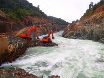
The Indonesian authorities requested that the hydroelectric resources of the Larona River be developed to the greatest extent possible. However, the river bed at Karebbe site is still 11m above sea level and there is no suitable site for a large dam downstream of this point. The river bed was therefore lowered to capture the remaining head in the river and develop it for power generation at Karebbe. After design and successful environmental permitting, the concept was executed as a drill-and-blast rock channel with a constant invert elevation one metre above sea level. The finished channel is 30m wide at the upstream end where the river flowed through a narrow gorge, and 40m wide further downstream where the valley widens. The excavation ends 2400m downstream of the dam, where the natural riverbed is also one metre above sea level. The tailrace modifications, under construction in Figure 6, were successful in lowering the tailwater level at the dam from approximately 16m to approximately 6m under the long-term average river flow, increasing the gross head for power generation by nearly 20%.
Proving the concepts
No precedent was found for the unique spillway arrangement, so SNC-Lavalin commissioned Northwest Hydraulic Consultants to construct and test a 1:50-scale physical hydraulic model. While the model flow patterns in the gated spillway bay and the side channels were generally as expected, it was difficult to contain the flow at the 90° intersection of the side channels and the steep chutes. Due to the tight project schedule, there was no time to search for a refined solution, but a rough-and-ready solution was found: triangular baffle blocks were inserted near the downstream ends of both collector channels and a wedge-shaped constriction was placed in the right bank collector channel only, as shown in red on Figure 2. Dynamic water pressures were measured at points in the physical hydraulic model to determine the design loading on the powerhouse roof.
The proposed hydro-combine arrangement was also unusual. A search of the world-wide literature revealed five precedents, the most recent of which were three dams in China. A technical visit was therefore made to inspect two of these dams and to meet the designer and operators. There were two significant findings from this visit:
• An extremely robust articulation joint detail was needed to avoid damage during spillway flows.
• Prototype measurements on the existing dams show that the dynamic pressure peaks applied by the turbulent flow to the powerhouse roof are randomly distributed in time and space.
Construction
To reduce the project schedule, a tender was prepared for the turbines, generators and ancillary equipment while work was still in progress on a Feasibility Study to prove out the concepts and to firm up the costs. A contract for the generating equipment was subsequently awarded to Andritz Hydro, who fabricated all the large steel components in Indonesia.
A contract for the preliminary civil works, including site roads, the river diversion works and the tailrace modifications, was then awarded to KPP, a consortium of Kajima of Japan and an Indonesian partner.
River diversion was carried out using a modified horse-shoe shaped tunnel. A 300-m thick concrete lining was constructed inside the 8.2 m tunnel to reduce hydraulic head loss. The tunnel inlet was equipped with a segmented gate and dedicated hoist, which were operated near the end of construction to successfully impound the reservoir. After impoundment, the tunnel was sealed with a permanent concrete plug. Curtain grouting was carried out inside the tunnel liner before river diversion, so only contact grouting was required after construction of the plug.
KPP also won the tender for the main civil contract, which covered construction of the upstream and downstream rockfill cofferdams, a concrete upstream cofferdam, the power intake, 73m high gravity dam and 2-unit 130MW power house. The two 5.5m diameter penstocks were supplied and installed by Andritz Hydro.
The dam was conceived and tendered as a roller-compacted concrete (RCC) structure overlaid with conventional reinforced concrete structures where required for strength or erosion resistance. However, there were two compelling arguments against using RCC construction:
• Placement of RCC in the dam would not be able to start until after completion of the penstock installation.
• The narrow river valley and the hydro-combine arrangement meant that each RCC placement area would be relatively small and would have a complex plan area.
At the request of the Main Civil Contractor, the dam material was changed to low-cementitious conventional concrete (LCVC). This allowed work to start independently on each dam monolith and greatly reduced the construction schedule for the dam component of the project.
Fly ash was used for 50% of the cementitious content of the LCVC. This reduced the carbon footprint of the project (since the ash is a waste product from a coal-fired power station in Java), and the heat generated by hydration (which reduced concrete cracking). Hydration heat rise was further controlled by limiting lift heights to 0.9 m and circulating river water in cooling water pipes.
In addition to the schedule advantage, the change of material allowed the conventional concrete (CVC) components to be better integrated into the dam. In general, the LCVC and CVC portions were placed as zones of different concrete mixes in the same lift and the reinforcement previously designed for the interface between the RCC and CVC zones was eliminated.
As can be seen from the construction photo, Figure 7, the powerhouse site was extremely congested because of the narrow valley and because the hydro-combine layout requires part of the spillway to be constructed on the powerhouse roof.
The steep valley sides would have made it difficult to develop a construction access road to the upstream side of the dam, so a 6m square opening was left in the base of a left bank dam monolith for construction access. This was subsequently plugged and grouted before installation of the Carpi membrane on the dam face.
Andritz Hydro won contracts for supply and installation of the gates and hoists, the ancillary equipment and the overall control system. ABB won the tender for the transmission line and switchyard extension.
Working in any developing country presents unique challenges, as does working in a remote location, but in addition, all contractors had to follow a new regional labour-recruitment procedure to provide all the surrounding villages with a fair share of the employment benefits generated by the project.
The labour force peaked at over 2000 people, the majority of whom had no previous exposure to the rigorous safety policies employed by both SNC-Lavalin and PT Vale. A joint safety team was established using SNC-Lavalin and PT Vale safety staff, and a safety mindset was inculcated into the workforce through worker indoctrination, provision of protective safety equipment, skill training and constant vigilance by everyone on site. When the project ended, the site had exceeded 9 million man-hours without lost-time injury.
Conclusion
The project was successfully completed, commissioned and handed over to the PT Vale operators at a ceremony on October 11, 2011.
The project satisfied several needs. The Client not only benefitted from the additional power, but the hydro-combine arrangement allowed for short penstocks and a generation system that responds rapidly to the highly variable power demand of the arc furnaces.
The failsafe spillway allows the reservoir to be operated continuously at a level only 0.5m below the dam crest and the tailrace modifications lowered the tailwater by approximately 10m. These features combined to increase the operating head and hence the energy produced by Karebbe hydro generating plant.
Reservoir clearing removed most of the potential for greenhouse gas production and in addition the project achieved a low carbon footprint during construction, partly by the use of concrete with a high content of high fly ash.
Graham Finlayson was the Karebbe project manager and can be reached at graham.finlayson@snclavalin.com. www.snclavalin.com