A new technology to meet the inter-tie needs of grids in critical urban centres is found in AMSC’s HTS based ‘Secure Super Grids’ cable system with a built-in fault current limiting feature. It is designed to be installed more easily, provide an enhancement in power capacity and fault current protection, and add security and reliability.
Under the banner ‘Secure Super Grids’ American Superconductor Corp is developing a high temperature superconductor based technology to address what is becoming an urgent need in large cities around the world – distribution network reinforcement with enhanced fault current protection, all in severely limited space. The solution devised by AMSC is claimed to answer all this need while also offering good value and increased reliability and security.
A first demonstration project is now underway as part of the process of replacing and hardening the electric power infrastructure, a strategy that focuses on grid reinforcement in the densely populated urban areas that are traditionally host to critical centres of finance, trade and government. It is being carried out under a contract with the US Department of Homeland Security and is led by AMSC in collaboration with the utility Consolidated Edison of New York city. The technology, which builds on HTS cable demonstrations during the last ten years, is applicable worldwide and can be applied to a variety of HTS cable designs by different cable suppliers.
The immediate challenge
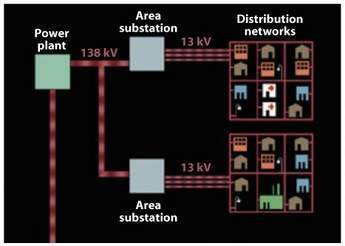
Many of the global challenges in electric power infrastructure can be illustrated by the example of Manhattan in New York City, one of the world’s most densely loaded areas and home to the USA’s most critical financial centre. Manhattan is currently served by Con Edison’s network distribution system, (Figure 1). Individual islands of 100 MW to 300 MW load are served at 13 kV using multiple underground feeds from an area substation, which consist, typically, of five 65 MVA 138-13 kV transformers and can serve about 150 MW of load. Con Edison’s security system standard requires an N-2 contingency: for example, no loss of load-serving capacity after the loss of two substation transformers.
One of the challenges associated with the distribution network concept is that there are no electrical connections between the individual islanded distribution networks. Consequently, during an emergency such as the loss of one or more 138-13 kV transformers at an area substation or the loss of one or more 13 kV feeds to the distribution network, the affected distribution network cannot rely upon or use excess load serving capacity at an adjacent distribution network. Another major challenge in New York is ongoing load growth and the difficulty of adding the power cables and substations in an already densely built and populated centre.
Con Edison plans to address these problems by deploying a third generation distribution system in which area substations are connected together by inter-ties consisting of high-capacity underground 13 kV feeders. In addition, the larger distribution networks could be broken down into smaller networks, each of which is served from multiple 13 kV sources, or busses. This concept would allow area substations to share excess capacity in emergencies and would decrease the number of 138-13 kV power transformers required at each area substation, while at the same time increasing the overall reliability of the grid – in effect sharing transformers across the network. In certain cases, Con Edison could avoid having to construct new substations. The configuration of these distribution feeders is shown in Figure 2. The cross connections should result in a significant increase in the reliability of the network.
The required capacity of these inter-ties is 3 kA – 5 kA, or 68 MVA to 113 MVA. This would allow area substations to share excess load-serving capacity and create a more secure delivery network for critical loads.
However, there are multiple obstacles to such a solution. These include facilitating the installation of increased distribution power capacity under city streets and preventing the growth of fault currents beyond limits set by existing breakers and other grid components.

Figure 1. Example schematic of an electric power network with islanded distribution networks. (Courtesy of Con Edison)

Figure 2. Schematic of proposed 3G electric power network for New York City, with distribution-level inter-ties between area substations and compact networks served by multiple sources. (Courtesy of Con Edison)
Installation of increased capacity
A first obstacle to the inter-tie solution is the large current capacity required. With conventional technology this would require a large number of copper cables occupying a significant amount of space. Because of the heat generated, they must be located near the surface, preferably embedded in thermally conducting sands and separated from each other and from pipes, gas lines and telecommunication cables. The existing underground infrastructure in urban centres such as Manhattan is already highly congested.
High temperature superconductor cables provide a solution. They dissipate no heat and emanate no electromagnetic fields, and do not disturb nearby infrastructure, so they can be installed deep underground, avoiding the surface infrastructure. Alternatively, they can be retrofitted through existing ducts or closely spaced in small trenches. HTS cables are lightweight – lighter than copper – and can be installed more cheaply.
Another major feature of HTS cables, illustrated by the Southwire (Ultera) Triax design shown in Figure 3, is that they can carry up to 10 times the power density of conventional cables, saving underground real estate and lowering installation costs. HTS cables carrying up to 3000 Arms at 13.2 kV are successfully operating in the AEP grid in Columbus, Ohio. They have also been developed for sub-transmission voltages up to 77 kV by Sumitomo Electric and Furukawa Electric and for transmission voltages up to
138 kV by Nexans. A 350 m, 34.5 kV cable by Sumitomo is operating in the Albany, NY, grid of National Grid. Other companies demonstrating HTS cables include LS Cable in Korea, Condumex in Mexico, and Chang-tong Cable and InnoPower in China. HTS cable technology is beginning to be deployed as a commercial solution in utility grids. In the longer term future it may also be applicable to longer distance connections, leading, potentially, to a ‘super grid’.

Figure 3. Southwire’s HTS Triax cable, showing the three co-axially wound phases around a central former, separated by insulation, all within a cryostat and external support tube. (Photo courtesy
of Southwire)
Fault current solutions
Another major obstacle to the implementation of the inter-tie strategy is that these connections, in general, will increase fault currents. The fault current, which arises in a grid when loads are short-circuited, is determined by the system voltage divided by the residual impedance of the grid without the loads. The residual impedance is usually dominated by transformer impedance, but also includes cable impedance and the output impedance of the generators. However, as more parallel connections are made, these impedances are reduced, so the potential fault current grows. It would grow anyway because of the addition of new generation and T&D installations to meet load growth. Fault currents in New York City and Long Island now exceed 60 000 A in certain transmission substations and 40 000 A in some distribution substations. These values approach today’s circuit breaker ratings, and they are inexorably rising as grids expand. Higher-rated circuit breakers are very expensive.
Another solution is to install additional impedance, usually series inductors, into the grid and this has been done by many utilities, but there is a limit to the effectiveness of this solution because as residual series impedance in the grid grows, the voltage drop over that impedance increases, resulting in voltage sag and system instability. Many utilities are rapidly approaching this stability limit, and a new solution is urgently needed.
HTS technology provides such a solution in the form of the superconductor fault current limiter (FCL), which is under development at a number of companies around the world today. There are many different designs including those based on an inductive principle or those using nonlinearity in transformer core magnetism (the ‘saturable core FCL’). A recent overview of the various types of FCLs has been published by M. Noe and M. Steurer (Supercond. Sci. Technol. 20 (20057) R15-R29).
Perhaps the most promising type for economic and practical application is the so-called ‘resistive’ FCL. The superconductor operates as a switch, introducing a high resistance whenever the fault current exceeds a predetermined value. It works because above a critical current, superconductivity is quenched, and the transport characteristics become resistive. For this reason HTS materials are often termed ‘smart materials’. The same characteristic renders them fail-safe, in contrast to some semiconductor FCLs that have been developed..
A fast switching version employing thin layers of HTS in the form of micron-thick films in a laminated wire structure has been developed. It can switch to a fully resistive state with currents only two or three times higher than their critical value, and the structure can absorb a large amount of dissipated energy during the fault.
A second generation HTS wire – the AMSC?344 superconductor – that achieves these properties is constructed around a central insert that consists of a substrate carrying the very thin HTS film. The laminate may consist of a high resistivity material like stainless steel to provide an adequate resistance for the current limiting effect. Low cost processes are also used to manufacture the substrate and deposit the HTS layer.
These 344 superconductors are critical to a successful FCL technology. The availability of the first production 2G HTS wire has enabled the first demonstrations of stand-alone FCL devices based on 2G wire switching. In January 2007, AMSC and Siemens announced a successful test of a single phase 13 kV class system with a 2.25 MVA rating for normal operation, and Hyundai has carried out a successful test of a 23 kV class system with an 8.3 MVA rating.
Although these standalone FCLs are a powerful solution, nevertheless some utilities would like to avoid the cost and footprint they entail, particularly in urban substations where space is at a premium.
The Secure Super Grid
AMSC’s Secure Super Grids technology was designed to provide additional inter-tie distribution links while meeting the requirement for a low-cost solution that can enhance power capacity, limit fault currents and be installed easily. It incorporates the fault current limiting behaviour of its 344 superconductors directly into the design of superconductor power cables, which avoids the necessity of a stand-alone FCL and can be readily applied to a variety of cable architectures for distribution and transmission voltages.
The solution involves systems and HTS wire innovations. The superconductor cable system is configured in a grid as shown schematically in Figure 4 and consists of a low-impedance, high-capacity superconductor cable with a conventional, but lower capacity copper-based shunt cable in parallel. Often, the latter can consist of existing cables in the meshed utility network. Optionally, a reactor can be placed in series with the shunt cable to adjust the total impedance of this branch. A standard fast switch, capable of opening within four cycles, is in series with the superconductor cable. This system is embedded in a utility grid with a characteristic grid source impedance ZS, one or more circuit breakers, and a load.
The system operates as follows: under normal operating conditions, the impedance of the superconductor cable is of order 1/6 or less compared to that of the shunt cable, so that the dominant portion of the current flows through the superconductor cable and there is no voltage sag from the conventional cable or its series reactor. When a fault occurs, the superconductor cable switches immediately to a resistive state, limiting the fault current. The superconductor cable is designed so that its resistance is large compared to the impedance of the shunt cable, so that the remaining fault current is diverted to the conventional cable (and its series inductor) and is finally limited by the total shunt impedance ZR. After four cycles, the fast switch opens, allowing the superconductor cable to recover to its superconducting state, which, with proper design, will take only minutes. During this time, if the fault has cleared, the conventional cable carries the power based on its overload rating.
After a few minutes, the recovered superconductor cable is reconnected to the circuit by closing the fast switch and it again picks up the majority of the power flow. If the fault does not clear during this time, the system circuit breaker opens to initiate the utilities’ standard protection operating procedure. Alternatively, the system can be designed to allow two full faults of up to four cycles, so that a first re-closure of the fast switch can be carried out within seconds, compatible with standard utility protection schemes.
The parallel conventional copper cable is not necessary in all situations. For instance, in longer cable runs of 5 km or more, enough wire may be available to absorb the fault energy of the full fault hold time without overheating until existing circuit breakers open. In shorter runs, the parallel cable or an existing parallel connection is necessary to allow the fast switch to open and still maintain current flow to mesh with the existing utility protection procedures.

Figure 4: Schematic utility grid with the SSG system consisting of a fault current limiting cable in series with a fast switch and in parallel with a conventional cable and optional reactor

Figure 5. Configuration of a hypothetical utility grid, based on an existing utility case, for modelling the behaviour of an SSG installation (green) between two transmission substations.
Installation in a utility grid
Detailed simulations of the dynamic behaviour of the Secure Super Grids system, in the context of existing utility grids, have been performed to confirm the concept. System operating parameters depend significantly on the specific utility grid configuration, as well as on cable length and rating, but designs reducing fault current by 10-50% are possible. A hypothetical example, modelled after a real situation in an existing grid, is shown in Figure 5.
Initially, a single transmission circuit (a 138kV cable) and a fairly extensive 69kV sub-transmission network connect the two substations shown. The 138kV cable has the capacity to transfer up to 230 MVA, but the 69kV sub-transmission system primarily exists to serve the various distribution substations in the area and is not designed for bulk power.
When a significant power source near transmission substation 2 is installed because of ongoing load growth, the utility will have a significant financial incentive to increase the amount of power that can be transferred in the direction of that substation, from which power can be provided to neighbouring regions or sold to a neighbouring utility. In this example, approximately doubling the amount of transfer capability would meet the system owner’s goals.
One solution is to add a second 138kV conventional cable that is electrically identical to the first. The problem is that the fault current levels at the substations are already at a very high level, and the addition would result in even higher fault current levels, with a corresponding increase in investment in circuit breakers, transformers and other fault current sensitive equipment.
An alternate would be to install a 138kV Secure Super Grids HTS fault-current-limiting cable system. With a single SSG circuit, the power transfer level can be increased to a much higher level than with a single conventional circuit. For the purposes of this study, a 2000A, 478 MVA cable was considered. This has over twice the capacity of the existing circuit.
In addition the SSG cable would create a much smaller increase in fault current level. and, because the SSG cable alone can supply the desired level of transfer capability, the system owner would have the option of opening the existing conventional 138kV cable, leaving the SSG cable as the only in-service transmission path. This approach would result in fault current reductions of over 27% at substation 1 and over 6% at substation 2 from initial levels. Comparing the SSG solution against the conventional solution option, the reductions in fault current are over 36% and 9% at substations 1 and 2 respectively, with similar increases in power transfer capability (Table 1).
The data in Table 1 show that it is possible to apply SSGs in a manner that will significantly increase power transfer capability while at the same time lowering fault current levels. It is considered to be appropriate to any situation in which increased power demand is accompanied by rising fault currents in urban environments where underground cables are required.
US DHS demo project
In May 2007 a $39m programme for the first demonstration of the SSG concept was announced by the US Department of Homeland Security. It is to be led by AMSC, with Con Edison as the host utility. The aim is to demonstrate a superconductor cable system that has the technical capability for installation as a substation-to-substation tie within Con Edison’s severely congested distribution network.
The project design will be for a 600 ft HTS cable incorporating the required fault current limiting attributes, set by the interrupting capability of existing substations, but within the HTS cable itself.
Cable design will be based on the Southwire Triax design (Figure 3) and the successful demonstration cable, a 13.2 kV superconductor, installed in the AEP power grid in Columbus, Ohio. AMSC will make the wire and acquire the refrigeration system, as well as design and supply the control system and components such as the fast switch. Southwire will provide the cable and terminations. AMSC and Con Edison, will co-operate in the full dynamic modelling of the cable.
Maximum operating current will be 4000 A, operating at 13.8 kV. Specifications for fault current reduction are being finalised but will be in the range of 25%. Other responsibilities of the project team include:
• Integrity/construction test criteria;
• Functional testing acceptance criteria;
• Training needs analysis;
• System descriptions and design basis documentation;
• Acceptance testing protocol;
• Testing and acceptance criteria;
• Integration engineering and design;
• Operation and maintenance procedures;
• Alarm response procedures;
• New construction standards and operating procedures jointly with Con Edison related to any of the new technologies being deployed;
• Installation, operation and testing of the system and equipment in accordance with Con Edison’s standard construction and operating procedures.
The project’s first phase, which is now underway, focuses on the development and operation of a prototype system, testing to be completed by the end of 2008. The second phase will focus on the deployment of the first SSG system in Con Edison’s power grid in Manhattan. Commissioning should take place in early 2010.
Project to develop a stand-alone FCL
AMSC and Southern California Edison, California’s largest electric utility, have announced a co-operative agreement award from the US Department of Energy to develop and perform in-grid testing of a transmission-voltage fault current limiter. It will utilise a design from Siemens that incorporates AMSC’s second generation high temperature superconductor wire.
AMSC will lead the project to develop a 3-phase, 115 kV stand-alone FCL It will feature a proprietary low-inductance coil technology from project partner Siemens that makes the FCL invisible to the grid until it switches to a resistive state upon the detection of a fault current. The demonstration will occur at a location operated by SCE. In addition to Siemens and SCE, the project partners include cable maker Nexans, the University of Houston and Los Alamos National Laboratory.
The project will be conducted in two phases. The first will focus on customising 7500 m of AMSC’s second generation HTS wire for the application, developing an advanced switching module, designing terminations, and manufacturing and testing a single-phase, transmission-voltage FCL in a laboratory setting. The second phase of the project will focus on manufacturing and testing the three-phase, 115 kV FCL in SCE’s grid.
The DOE, through its National Energy Technology Laboratory, is to provide AMSC with approximately $3.1 million in federal funding through completion of the first project budget period, expected to end in September 2008. Upon successful completion of key project milestones and sustained execution of a viable business strategy, as much as $9.7 million in additional DOE funding may be made available to AMSC for continued implementation of this five-year project through to September 2012, subject to availability of funds.
Earlier this year, AMSC and Siemens announced that they had achieved commercial-grade performance levels for a medium-voltage FCL. The test was conducted on a single-phase, 2 MVA FCL that operated at a 7.5 kV, which corresponds to a 13 kV class of three-phase power equipment. The FCL suppressed the current during a fault by up to twenty-five times. AMSC and Siemens formed a strategic business alliance in February 2005 to develop HTS fault current limiter technology.