Funding made available by both the Victoria State and Australian Federal Governments for the demonstration of Low Emission Technologies is enabling the implementation of pilot brown coal (lignite) drying technology at unit 1 of the International Power managed Hazelwood power station. This will dry the run of mine (ROM) (raw) brown coal from above 60% moisture content to approximately 12% moisture content in an initial 50% feed train. It is the core component of a major upgrade programme, Hazelwood 2030.
The Hazelwood 2030 project provides an opportunity for the first commercial application of WTA lignite drying technology (see pp 17-21) in a pilot unit. Alstom and Hazelwood Power have entered into a contract to convert unit 1 of the existing Hazelwood power plant to mixed 50% dried brown coal and 50% ROM brown coal firing as the first phase.

Above, the Hazelwood plant today, and below, visualisation of the plant with WTA added
Hazelwood 2030 centres around a project, focused on two of the station’s units, to boost efficiency, reduce CO2e intensity, and extend the life of brown coal fired units at Hazelwood. The units are over 40 years old and will be upgraded through a combination of a “conventional” major equipment retrofit programme, coupled with the installation of “cutting edge” equipment that will demonstrate the new RWE developed lignite drying technology on an industrial scale. The project brings together international and Australian companies from the private sector partnering with government to demonstrate and prove the novel technologies involved and deliver a commercial project.

The WTA facility is shown to the right of the plant
The Hazelwood 2030 project also involves the construction of a pilot carbon capture plant, scheduled to be operational in late 2008.
Genesis of 2030
Hazelwood 2030 arose through a combination of factors that came together at the right time for the various parties involved.
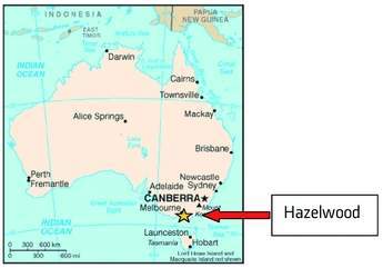
The Hazelwood power station is situated in the Latrobe Valley region of the State of Victoria (about 150 km east of Melbourne, Figure 1). It consists of eight non-reheat units with a nominal rating of 200 MWe that were commissioned from 1964 to 1971 and is located in a “mine mouth” location. The Latrobe Valley region contains huge reserves of brown coal at very shallow depths and delivers a very low cost fuel to the power station by global standards (<0.30 euro/GJ). The fuel has very low sulphur and low ash content but has a moisture level averaging over 60%. This large, low cost source of energy is thus not an exportable fuel resource but, as a fuel source for “mine mouth” based power generation, it delivers one of the major competitive advantages to the state’s large industrial economy.
Hazelwood power station was originally developed by the then state-owned monopoly utility. During a privatisation phase of the electricity industry in Victoria, Hazelwood was majority purchased by International Power plc of the UK in 1996 in partnership with a consortium of banks. It is currently managed
by International Power on behalf of the partnership. The sale of the power station included the attached open cut mine. Since assuming ownership of the asset, IPR has invested in extending the station’s life, improving output, enhancing its environmental performance and boosting availability.
The Hazelwood 2030 project needs to be seen in terms of the current Australian economic and political context.
Australia is the only country in the world to occupy a whole continent (Figure 2). It has a land mass area around that of all Europe or the continental US; and a population of around
21 million people. Its economy has enjoyed very strong growth over the last 20 years and per capita GDP is above that of major European economies.
Whilst the economy and employment in Australia are heavily based on service industries (>70%), a significant proportion of Australia’s export income is derived from its extensive minerals resources. In particular, Australia is the world’s largest exporter of coal and also a significant exporter of LNG and uranium. Coal as a low cost source of energy also underpins
the global competitiveness of Australia’s manufacturing and minerals processing industries. As such, Australia is dependent on coal and it is therefore in its strategic interest to ensure “clean coal” solutions are developed and deployed.
Politically, CO2 emissions have become a significant issue over the past two years. Australia’s basic policy framework is to work on reducing emissions without compromising economic growth. Consequently, there are both significant economic and political drivers to invest resources in concepts such as “clean coal”, carbon capture and storage, and low emissions technology. Whilst Australia did not ratify Kyoto, it did join the AP6 initiative and has been very active at both federal and state
levels in providing significant funding for both research and large-scale industrial develop-ment/demonstration of such technologies. Significantly, major private industry groups such as the coal, mining and power industries, as well as individual companies, have taken an active role and contributed significant resources over and above that provided by government.
As part of the federal government’s policy to support the development of new technologies to reduce CO2 emissions, it established the “Low Emissions Technology Demonstration Fund” (LETDF) (see MPS, May 2007, pp 44-45), to which the federal government has committed Aus $500 million, with a requirement that industry contribute another Aus $1000 million.
International Power’s Hazelwood 2030 project – with an estimated total project expenditure of approximately Aus $370 million – has received Aus $50 million from the LETDF. The project has received another Aus $30 million from the Victoria state government’s ETIS (Energy Technology Innovation Strategy) scheme, which aims to foster “cleaner” use of the Victoria’s abundant and low cost brown coal resource that underpins a significant proportion of the state’s manufacturing based economy. In addition International Power is investing approximately Aus $290 million of its own resources.

Figure 1. Location of Hazelwood power plant

Figure 2. Illustration of
relative land mass of Australia
In May 2007 Alstom submitted design and costings for the project and in September 2007 the notice to proceed was issued.
Key features of the WTA and retrofit project can be summarised as follows:
Unit 1
• Installation of new turbines. Steam extraction for WTA supplying 23kg/s. Unit output increased to between 215 and 217 MWe, with the same steam flow as the original design.
• Installation of boiler feed water heaters providing 3% improvement in unit boiler efficiency.
• Installation of a WTA fluidised bed drier sufficient to provide the fuel for 50% of the thermal heat input required for 50% co-combustion of dried brown coal (DBC).
• Conversion of boiler and adaptation of the firing system to 50% co-combustion of dried brown coal and ROM brown coal.
• Implementation outage scheduled for 4Q 2009.
Unit 2
• Installation of new turbines – unit output increased to 220 MWe, again with the same steam flow as the original design.
• Installation of boiler feed water heaters providing 5% improvement on unit boiler efficiency.
• Implementation outage scheduled for 2Q 2009.
WTA backfit
The existing Babcock & Wilcox designed boiler of unit 1, which has been chosen for implementation of the WTA technology, originally went into operation in 1964. The existing firing system is a typical raw brown coal firing system with eight beater wheel mills feeding a rectangular furnace arrangement.
The high coal moisture and the steam parameters provided by this drum type boiler contribute to the poor cycle efficiency and the high CO2 emissions currently experienced in operation.
The current unit 1 key data are as follows:
• steam pressure at the turbine inlet valves, 10.4 MPa abs;
• steam temperature at the turbine inlet valves 540°C;
• 100% BMCR steam flow at the turbine inlet valves 208.6 kg/s;
• final feedwater temperature 145°C;
• furnace cross section of 11.70 m x 15.56 m = 182.1 m2 and a furnace height of 22.70 m.

Figure 3. Schematic of Hazelwood WTA fine grain drier process

Figure 4. General arrangement of Hazelwood WTA fine grain drier plant
The major source of the efficiency improvement to be realised by this project is the conversion of the Hazelwood unit 1 to co-fire dried brown coal, with installation of the WTA fine grain fluidised bed pre-drying technology. In the case of Hazelwood, the water content of the raw lignite fuel is in excess of 60%.
For Hazelwood unit 1, the WTA unit will initially produce the required quantity of pulverised fuel at the required moisture content and fineness to supply 50% of the heat input needed for the modified boiler to produce a steam flow of 208.6 kg/s.
The process will entail fine grinding of the ROM brown coal to <2mm and subsequent utilisation of a steam heated fluidised bed to dry the coal. The heat for the drying process will be drawn from a suitable extraction point on the steam turbine of the same unit (flow approx. 23 kg/s at low pressure and low temperature), with the heat-transfer taking place in tube bundles located inside the fluidised drying bed. The condensate associated with this extraction steam is then returned to the boiler feed system after passing through the WTA.
Figure 3 provides a schematic of the process to be employed at Hazelwood.
The raw coal with a moisture content of up to 62% is ground from a size range of 0 to 80 mm down to a size range of 0 to 2 mm in two hammer mills connected in series. The subsequent drying in the fluidised bed further reduces the grain size, resulting in a dry (12% moisture content) coal with a grain size of <1 mm and only about 5% having an oversize at 1 mm.
The WTA plant will be arranged to the side of the existing unit 1 boiler as shown in Figure 4, and photograph, p22.
The dried brown coal coming from the WTA system will be stored in a silo. The storage capacity of the silo is sufficient for at least 4 hours dried brown coal operation. The dried brown coal silo has six outlets, one each for the supply of the dried brown coal burners.
There are six separate and identical conveying lines from the silo outlet to the dried brown coal burners.
Rotary feeders and downstream screw pumps with variable speed control are used for feeding the dried brown coal into the pulverised fuel duct and to the burners.
The rotary feeder introduces the dried brown coal into the screw pump feed box from the silo. The screw pump transports the dried brown coal continuously within the screw pump discharge box to the burners. During this transportation, the dried brown coal is mixed with conveying air which is introduced via a compressed air nozzle.
Leakage air from the conveying air is discharged from the screw pump feed box and de-dusted by leakage air filters on the roof of the silo. The rotary feeder and the screw pump are pressure shock resistant for 10 bar overpressure.
The conveying air is produced by six rotary piston blowers, each independently associated with a feed line. This is so that a defined conveying airflow volume in the pulverised fuel duct to the burners is ensured. The rotary piston blowers are designed for the conveying air in the pulverised fuel duct plus leakage air to the screw pump.
After mixing of the conveying air and dried brown coal in the screw pump discharge box the temperature in the pulverised fuel duct to the burners is about 60°C. The six pulverised fuel ducts to the dried brown coal burners are designed for a flow velocity of approximately 28 m/s in the ducts at the entrance of the burner.
Due to the different nature of the mixed firing that will occur in the boiler in the future from what has gone before, as a result of the co-firing of 50% dry brown coal with the existing raw brown coal, the modified firing concept was verified in a CFD study, which compared the current 100% raw coal firing system with the 50% co-firing solution (Figure 5).

Figures 5a,b. CFD model for 50% co-firing

Figure 5b.

Figure 6. Upper diagram: new turbine configuration. Lower diagram: existing turbine configuration

Figure 6
In order to accommodate the new firing arrangement two mills will be decommissioned. Six new dried brown coal burners with a firing capacity of approximately 55 MW each will be supplied and arranged in the evaporator walls.
In both the front wall and the rear wall, two dried brown coal burners (Figure 6) will be arranged in the compartment of previous ROM burners 1 and 5. The other two dry coal burners will be integrated in each of the sidewalls.
Each dried-brown-coal burner consists of a central core air tube with an integrated LPG pilot burner. This is surrounded by the annular dried brown coal cross section for the dried brown coal/conveying air mixture and the circumferential air for the main secondary air.
Burners of this design have displayed many years of successful operation in dried-brown-coal fired power stations, in dried brown coal start-up firing systems, in smaller bituminous fired boilers with dry-bottom ash removal and in slag-tap furnace firing systems.
The air and pulverised fuel outlet velocities aim to attain a good mixture and a high flow pulse in the furnace. The secondary air, fed by the circumferential air and the core air to the dried brown coal burners, is measured and controlled individually depending upon the firing rate.
For the reconstruction of the existing raw brown coal firing system to a low NOx firing system with dried brown coal at Hazelwood unit 1, the firing system design was undertaken for a total air ratio of lambda = 1.20 at furnace end and with a substoichiometric main combustion zone. The air heater ratio is fixed for 85% in the design conditions representing the basis for the design.
The cold air quantities to the boiler are represented by the small amount of conveying air from the rotary piston air blowers (approx. 3% of total air) and the false air to the furnace depending largely on the condition of the existing equipment.
The close-coupled overfire air nozzles are arranged close above the second level of the dried brown coal burners to allow for the possibility of a quasi burner internal air staging. Air staging in the furnace is done by one overfire air (OFA) level at about +21 m.
Thus, approximately 25% of the total combustion air is branched off from the hot air header after the air preheaters and is later added in the overfire air level. The nine over fire air nozzles are located in the front wall and the left and right side wall.
In order to control the combustion temperature in the furnace, a flue gas recirculation system using de-dusted flue gases taken off downstream of the electrostatic precipitator will be installed. At the maximum dried-brown-coal co-firing rate corresponding to 50% heat input from the dried brown coal at BMCR, approximately 20% of the overall flue gas volume will be recirculated via a flue gas recirculation fan.
The flue gas recirculation flow is measured and controlled separately.
Testing of Latrobe Valley brown coal at RWE’s Frechen prototype WTA plant in Germany has produced encouraging results, IP reports.
Turbine retrofit
The existing turbines on Hazelwood units 1 and 2 are the originally supplied AEI turbines (an antecedent Alstom company) installed in the early 1960s. The units have identical tandem compound turbines comprising a single flow HP, a combined IP–LP and a double flow LP cylinder (see Figure 6).
The station draws its cooling water from a pond, which has become warmer as the plant has been extended. During the summer months the turbine exhaust pressures can rise to 21.3 kPa abs. resulting in less efficient operation of the LP turbines and a reduction in unit power output.
With one of the objectives of the Hazelwood 2030 project being to improve the unit 1 and 2 efficiencies while maintaining the current steam flows, a number of scenarios were investigated by Alstom to achieve the optimal turbine configuration with the technologies available.
A significant consideration was the requirement for higher steam extraction from the turbine and additional auxiliary loads for the coal drying equipment and other auxiliaries planned for unit 1.
Alstom finally opted for a two cylinder retrofit solution.
The two-cylinder retrofit solution (see Figure 6) is based around a new HP turbine and a new IP–LP turbine arranged to occupy the existing HP and IP–LP turbine positions and modified lower half LP exhaust frame. The HP turbine is fitted with close-coupled HP steam valves to provide full arc admission.
The new IP–LP turbine effectively replaces the three existing Baumann exhausts with one larger conventional exhaust using a proven modern 901 mm exhaust blade with an exhaust area of 9.6 m2. The new IP–LP turbine is designed to match up to existing interfaces with extraction pipework connections, No 2 bearing pedestal and lower half LP exhaust frame. Modifications are required to the lower half LP exhaust structure to accommodate the larger exhaust blading and to ensure adequate flow area into the condenser steam space.
The replacement HP turbine (Figure 7) uses a two casing design with 25 stages of reaction type blading and an extraction belt for the final HP feedwater heater.

Figure 7. HP turbine retrofit module

Figure 8. Typical HP turbine with close-coupled valve chests

Figure 9. IP-LP turbine retrofit module
The outer casing is of conventional design with a horizontal joint and bolted flanges.
The inner casing is horizontally jointed with the two halves held together by the Alstom shrink ring closure system. This method of construction ensures the casing remains circular under all thermal conditions, avoiding damage to steam path radial seals. The inner casing is centreline supported within the outer casing and positioned transversely by vertical keys in the bottom half.
Steam is admitted to the HP turbine through two HP valve chests each containing one stop valve and one governor valve. The chests are close coupled to the HP turbine casing with one chest on each side of the unit (Figure 8). The scope includes extending one of the main steam pipes to the opposite side of the turbine foundation. The turbine is configured for full arc admission.
The new IP–LP turbine (Figure 9) will be supplied and positioned in the space vacated by the existing IP–LP turbine. The new IP–LP will interface directly with the existing No 2 bearing pedestal, extraction pipes and lower half LP exhaust frame.
The IP–LP turbine retrofit comprises a new “IP” outer casing with stationary blade carriers, new welded IP–LP rotor with 11 stages of rotating blades. A new LP exhaust hood, new LP exhaust diffuser and all the components needed to modify the lower half exhaust frame are also included in the module supply (stiffening bars, plate material etc). The last stage blade is 901 mm in length.
The new LP exhaust hood is designed to direct the top half exhaust flow into the second condenser (Figure 10).
Modifications are required to the lower half LP exhaust frame to accommodate the larger LP exhaust and new diffuser. This will also ensure that the exhaust steam in the lower half has free access to the first condenser.

Figure 10. Exhaust flow into condensers with single exhaust IP–LP

Figure 10.

Figure 11. New diffuser fabrication
Figure 11 shows the modification of the LP lower half frame and new diffuser fabrication.
The redundant elements of the Baumann exhaust will be removed and a new exhaust diffuser with exhaust spray water manifold and last stage stationary blade ring will be installed.
The new IP–LP rotor will be of welded construction comprising two or more separate sections welded together using proven procedures. No centreline bore is required for verification of bore properties during manufacture.
The leading edges of the last stage blade will be hardened to provide resistance to erosion by water droplets in the steam flow.
The replacement IP–LP outer casing will be fitted with additional openings to permit the extraction of steam for the coal driers. For unit 1 the scope will include a bled-steam isolating valve and pneumatically assisted non-return valve to protect the turbine against potential overspeed and water ingress situations. For unit 2 the extractions will be blanked pending potential retrofit of a WTA unit at a later time.
The bled-steam isolating valve for the extraction feeding the coal driers will be controlled to maintain pressure levels in the turbine to ensure an adequate supply of steam to the feedwater heaters.
The turbine retrofit necessitates modifications and upgrades to the existing turbine auxiliary systems to accommodate the replacement units.
The existing mechanical turbine governing system will be replaced by the Alstom P320 TGC two-channel redundant control system. The P320 TGC governing system is a programmable microprocessor based control system, which is installed as standard equipment on current Alstom steam turbines.
The governor will also be used to provide the control logic for the upgraded turbine systems. The governor may be operated through either the plant DCS or its own PC based operator workstation.
No major changes to the lubricating oil system are anticipated. It will however be necessary to adjust the oil flows to the new turbine bearings.
The present relay oil system will be upgraded to provide higher pressure oil for the actuators on the new HP steam admission valves. A redundant booster pump will take oil from the existing relay oil manifold and raise its pressure. The scope includes hydraulic dump valves to ensure rapid closure of the steam valves in the event of a fault.
Modification of the existing system to interface the new HP front and rear glands and new IP front gland is required. An extension of the existing system to provide steam sealing of the LP rear gland is also necessary. The scope includes a desuperheater to condition the steam for the LP gland. The upgraded gland sealing system will be controlled by the newly supplied governor.
A completely new turbine drains system comprising new manual master and manual martyr valves and new pipes between the upgraded turbine and existing drains flash vessel will be supplied. Separate drains will be provided for each HP steam chest, the HP cylinder and the HP–IP cross-under pipe.
Modification of the existing forced air-cooling system to suit the requirements of the replacement turbine will be undertaken. Two exhaust pipes on the HP cylinder each fitted with double isolating valves to vent the cooling air to atmosphere will be provided. Existing connections to the LP casing will be replicated on the new turbine. Cooling time is expected to be similar to that achieved on the existing installation.
In order to protect the deaerator from excessive pressure when unit 1 is operating at full load with the coal dryer out of service a pressure control valve is provided for installation in the feed to the deaerator.
On unit 1, additional bled-steam isolating and non-return valves will be installed in the extraction lines feeding the coal dryer.
Operating modes
Following the modifications to Hazelwood unit 1 the following three operational modes will be possible:
• Mixed firing – 50% heat input from dried brown coal, 50% heat input from ROM coal, such that unit 1 will operate at 100% MCR;
• 50% dried brown coal only – with sufficient heat input for unit 1 to operate at a minimum of 50% MCR; and
• Raw coal only – using the remaining six ROM coal mills to achieve between 80% and 100% MCR depending on coal quality, mill availability and vacuum constraints.
Improvement in greenhouse intensity
The Hazelwood 2030 demonstration project will deliver a greenhouse intensity of approximately 1.27 tCO2e/MWh for unit 1, compared with the current greenhouse intensity level for units 1 and 2 of about 1.61.
The improvement in greenhouse intensity is realised through the four key areas of the project:
• modifications to the existing units (unit 1 & 2 turbines and unit 1 boiler works);
• implementation of the WTA system for 50% dried brown coal co-firing (unit 1);
• boiler feed heater; and
• performance recovery.
Overall, the combined modifications included in this first stage will contribute to reducing the unit 1 greenhouse intensity to less than 79% of the existing value. This can only be achieved by the combined and integrated approach to the implementation of the turbine retrofit, installation of boiler feed heaters and the co-combustion of dried brown coal, up to 50% of fuel input.
The authors are with Alstom, and located in the UK, Australia and Germany, respectively