Generator inspection is a critical process in ensuring long lifespans of reliable performance, but interruptive processes can be a headache for system operators. However, advances in robotic inspection techniques have allowed comprehensive inspections to be carried out with significantly reduced down-time and improved repeatability of results. By Malcolm Dunkley, lead mechanical engineer, BRUSH, UK
Generators are a relatively low- maintenance component in the power generation system, but they are also one of the most critical, so it’s important for operators to follow the recommended inspection programme.
A traditional inspection of a generator, which requires the rotor to be removed, takes between 20 and 25 days. While this is a significant outage to plan around, neglecting to carry out the scheduled maintenance and therefore failing to identify an issue that might lead to a generator breakdown is a much riskier strategy. A generator that is allowed to break down will almost always require a rebuild, a process that takes several months and a significant financial outlay to carry out.
Given the importance of inspections, a great deal of work has been done to speed up the process and the state of the art approach is now robotic inspection, which avoids the need to remove the rotor but still offers the same inspection elements as the manual approach. In fact, mechanisation even delivers potential benefits over the labour-intensive alternative.
Robotic inspection
Of the 20-25 days it takes to carry out a traditional generator inspection, between five and 10 days – depending on ease of access at any given site – is spent on mechanical disassembly, in other words safely extracting the rotor to allow personnel to access the inside of the stator.
However, between the rotor and stator of any generator is an air-space, typically between 10 mm and 60 mm depending on the size of the unit, and the emerging technique of robotic inspection makes use of this to gain access and test internal componentry without the need for disassembly.
A number of competing robotic inspection systems have been developed, but here we will look at the Robotic Generator Inspection System (RoGIS), in part developed by BRUSH, to illustrate how the systems work.
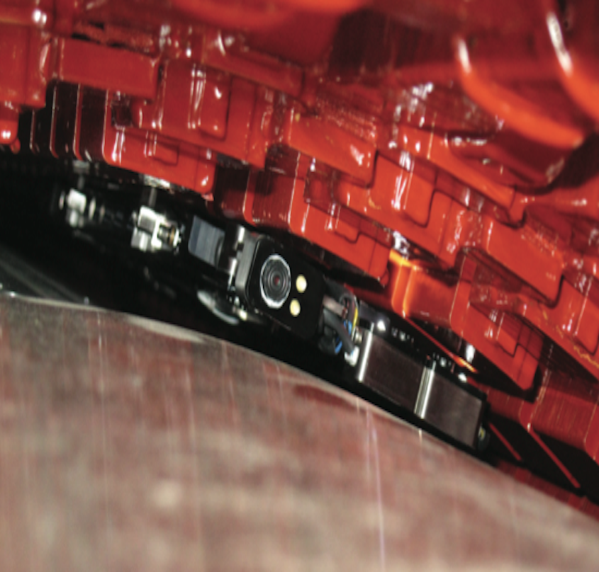
RoGIS consists of a Docking Station (DS) and a remotely-operated Generator Inspection Vehicle (GIV). The DS is mounted on the end cap (retaining ring) of the rotor and can be rotated to any position, so that the GIV can be aligned with every stator slot without needing to move the rotor.
The Generator Inspection Vehicle is designed to fit in the space between the retaining ring and the core and can be used with any generator having a radial clearance between the retaining ring and the core of 17 mm or greater, so almost every unit with an output of 10 MW or greater. It is launched from the Docking Station, transferring directly to the stator core to which it attaches magnetically, before travelling axially along the core, between the step irons at each end.
The GIV is controlled by the operator using an accompanying software package and is steered automatically to maintain alignment as it travels through the generator.
The axial position of the GIV is relayed in real time to the operator via the computer and is pre-programmed by the operator to prevent overshoot at the end of the core.
The GIV is fitted with a manual recovery system, for extraction from the air gap in the event of a power failure.
There are three elements to a detailed generator inspection that RoGIS can perform: visual inspection; stator wedge tightness testing (WTT); and Electromagnetic Core Imperfection Detector (EL-CID) testing. Here we will look at each of these techniques, why they are all required to give a comprehensive view of the condition of a generator and how robotic systems are designed to carry them out.
Visual inspection
The appearance of the internal surfaces of the rotor and stator can provide a lot of information about the condition of a generator, and often it is the visual inspection that can deliver the advance warning of issues that might develop further down the line.
The GIV is equipped with four cameras. The first is angled forwards along the air gap, providing visibility of the rotor main body, including the balance plugs, as well as the stator core. The second looks downwards, directly onto the surface of the rotor, allowing inspection of the ventilation slots. Finally, two cameras aimed outwards provide direct views of both sides of each stator ventilation slot.
Stators can typically have between 42 and 72 slots, so the vehicle will make this number of out-and-back journeys in the course of an inspection. Ventilation slots are placed at regular intervals along the length of the stator. So, for example, a 5 m long core, with ventilation slots every 50 mm, would have 7200 ventilation slots to inspect.
A combination of video analysis software and oversight from a qualified engineer is used to ensure that this potentially laborious process is carried out quickly and efficiently without risk of issues being missed. In reality, many of the issues the engineer is looking for – see box, left – will normally affect large areas in the same way, so there is rarely a needle-in-a-haystack scenario where a generator that is in otherwise very good condition will have a highly localised issue in just one ventilation slot for example.
Stator wedge tightness testing (WTT)
A loose wedge in the stator will mean movement in the coils, which can lead to mechanical abrasion of the groundwall insulation, accelerating the deterioration of the generator and potentially causing the generator to fail.
The RoGIS tests wedge tightness acoustically, tapping the surface and listening for variations in the sound heard upon impact. Traditionally this was carried out by hand by an engineer, although mechanised tap testing is now the preferred approach, even for rotor-out inspections.
The GIV has the facility to conduct tightness tests on every wedge in every stator slot, transmitting the audio in real time to the operator via the computer.
Mechanising the test ensures exact repeatability of the force and position of the impact on each wedge. Today, the audio is also normally analysed by software rather than solely by ear, although engineers do also listen to the audio feed to double-check the results.
The software compares the sound of each impact with results generated from extensive testing on a range of wedging systems with various levels of tightness. This comparison allows differences in individual results to be identified quantitatively so the exact degree of tightness can be determined.
The parameters of the test are adjustable in terms of the depth of the slot lips being tested, the number and length of wedges in the slot, and the number of taps per wedge.
The results are then presented as a relative tightness index (TI) map, see example above, making it immediately clear where any issues lie in both axial and radial position. As well as clarifying whether maintenance works are required, this will also inform the repair team as to exactly where attention is needed.
Electromagnetic Core Imperfection Detector (EL-CID) testing
Developed in the 1970s, electrical core testing is standard practice for generator maintenance. It is a means of investigating the stator for soundness of its interlaminar insulation and works by inducing a circumferential flux. Any damage to the insulation allows a circulating fault current to flow (see diagrams below) and these changes can be picked up by a sensitive electromagnetic sensor – a Chattock potentiometer – positioned inside the stator.
To carry out the test, a bundle of conducting wires are passed through the air gap between rotor and stator and these form part of a current loop that runs around the outside of the stator core. Several turns of #10 American Wire Gauge (AWG) insulated wire are used and the current in this loop creates the circumferential flux required for the test.
The GIV moves the potentiometer axially along the stator core while readings are continuously recorded. Before the test, the sensor is calibrated for a situation in which no current is flowing in the core, so for an undamaged section of core, the reading should be zero.
In practice, fluctuations resulting from background signals and small insulation imperfections are normally present, but any core faults will give a reading large enough to be easily visible above the noise.
This allows a fault current graphs to be created for each slot in the stator, which build into a complete map of its electrical condition.
Maximising availability
Robotic inspection is an important advance for generator performance around the globe, as reducing the length of outages associated with carrying out scheduled inspections will make skipped inspections harder to justify.
While the technique in its basic form has been in existence for more than ten years, major developments in both hardware and software have taken place, drastically increasing the effectiveness and reliability of the process.
The performance of a generator can be measured in terms of reliability and longevity and a pro-active maintenance programme is essential. By making the process quicker, easier and cheaper, robotic inspections are set to have a significant positive impact on in-situ generator performance around the world.