Xueqing Zhang discusses the technological developments, advantages and applications of rubber dams
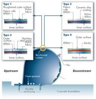
Figure 1
Rubber dams are flexible hydraulic structures. A rubber dam mainly consists of four parts: (1) a rubberized fabric dam body; (2) a concrete foundation; (3) a control room housing mechanical and electrical equipment (e.g. air blower/water pump, inflation and deflation mechanisms); and (4) an inlet/outlet piping system. The dam body is fixed onto a concrete foundation and abutments by a single or double-line anchoring system. A typical foundation of the rubber dam has upstream and downstream cutoff walls to lengthen the groundwater seepage path and thus reduce the uplift force of ground water.
The rubber dam concept was developed in the 1950’s by N.M. Imbertson of the Los Angeles Department of Water and Power and manufactured as Fabridams by the Firestone Tire and Rubber Co. The first Fabridam was installed on the Los Angeles River, California, for groundwater recharge and flood mitigation. This early dam was filled by water, and its height was regulated by a siphon (Lu et al., 1989). In 1978, bridgestone Corporation (Bridgestone) introduced an air-inflated rubber dam. The rubber dam has experienced continuous improvements and innovations since then.
Structural simplicity, flexibility and proven reliability are key considerations in the use of rubber dams for multiple purposes. Up to now, thousands of rubber dams have been installed worldwide for irrigation, water supply, power generation, tidal barrier, water treatment, flood control, removal of sediment deposits, environment improvement and recreation. Table 1 shows examples of rubber dams installed in different regions of the world. There are a number of rubber dam manufacturers, for example, Bridgestone and Sumitomo Electric Industries Ltd. (Sumitomo) in Japan, the Yantai Tiansheng Rubber Dam Co. Ltd. in China, Obermeyer Hydro, Soluziona Engineering and Dyrhoff AS.
A unique characteristic of the rubber dam is its ability to function as a reliable crest-adjustable water gate. When inflated by a medium (air, water or their combination) it rises to retain water; when deflated by releasing the medium, it flattens onto the foundation, completely opening the channel for free passage of water. The rubber dam can also be adjusted to operate at intermediate heights to meet the needs for different upstream/downstream water levels in different time.
Air is used more often than water as the filling medium for the following reasons (Bridgestone, 1994):
* Water and water-borne debris can corrode and clog pipes.
* The design and construction of air-filled dams are simpler.
* Water-filled dams require a more complex piping system and often need a pond to store water for filling the dams when river water levels are low.
* The inflation and deflation time of an air-filled dam is much shorter than that of a water-filled dam of the same size.
* Due to the weight of water, the water-filled dam has a squat shape, requiring more rubber material than an air-filled dam of the same height.
* The circumference of a water-filled dam is about 4.8 times its height, compared to 3.5 times for an air-filled dam. To accommodate the dam body, the foundation of a water-filled dam must be wider than that of an air-filled dam of the same height.
However, air-filled dams are less stable and suffer more from vibration than the water-filled ones, which are more preferable when hydraulic conditions are more demanding (Markus, 1995).
Advantages of rubber dams
Long span and adaptable to different side slopes
Long rubber dams can be installed in broad rivers without piers. They are adaptable to virtually any side slope angle. Little work is needed to modify riverbanks. While for a steel gate, intermediate piers are generally needed for about every 20m. Furthermore, steel gates cannot be installed unless the side slopes are vertical.
Short construction period
Compared with a conventional steel gate the rubber dam body is lighter and easier to handle. It can be fabricated in one piece at a factory and rolled up for easy transportation to the dam site. The rubber dam only requires a simple light foundation with a 10 to 15cm recess, while steel-gates normally have a 50 to 80cm recess (Bridgestone, 1997a). The construction of the concrete foundation and installation of the rubber body can be completed quickly, easily and economically. A single or double-line clamping plate is used to anchor the rubber body onto the foundation.
Easy maintenance and repair
Minimal maintenance is needed for rubber dams. There is no need for painting, greasing, or lubrication. With a steel gate, various maintenance expenses are needed, such as removal of rust, repainting and changing of hydraulic oil. Table 2 shows the maintenance operations for Dam No. YLN 189 in Hong Kong from June 1993 to September 1995. The average maintenance time was about three hours, while the total time spent on maintenance (129 hours) was only about 0.6% of the total operation time (approximately 19,992 hours). Techniques used for repairing automobile tires and conveyor belt can be applied to repair damages to the rubber dam body.
Low project life cycle cost
The life cycle cost of a rubber dam project is low due to prefabrication of the dam body, little modification to riverbanks, light concrete foundation, quick construction and installation, easy operation and minimal maintenance. Table 3 provides the construction, operation and maintenance costs of the Yuen Long Inflatable dam in Hong Kong, China.
Earthquake resistant
The simple and light upper structure, uniform load on the rubber body, and light concrete foundation make a rubber dam project more earthquake-resistant than other structures serving similar functions. It is more adaptable in sensitive ground conditions where the foundation may subside unevenly. In fact, many rubber dams are installed in Japan, a place prone to earthquakes.
Adaptable to adverse conditions
Rubber dams can be placed in adverse environments. For example, in the Santa Ana River rubber dam, California, US, steel gates were not selected because of the corrosive environment: (1) The dam is only 19 km from the ocean and the major component of the base river flows is wastewater effluent; (2) The river has a high sediment transport capability, which can clog gate operators and abrade steel gates and hinges (Markus et al., 1995)
The rubber dam is operable in very cold climatic conditions, under which a steel gate may be inoperable. For example, both vertical lift and radial-type spillway gates present operational difficulties under icy conditions. They may be unable to operate due to increased hydrostatic loading and frictional resistance caused by ice. In extreme cases, the gate may be overwhelmed by ice and frozen in place (Sehgal, 1996). Air-filled rubber dams do not suffer such problems and can be fully operational. The rubber dam absorbs the impact from drift ice by its capacity to undergo deformation during ice passage and regains its shape thereafter. Furthermore, a rubber dam also reduces the problem of flooding upstream due to the buildup of ice at a conventional hydraulic structure. In rivers prone to icing, rubber dams with sloping sides and fewer intermediate piers are preferred over multi-pier water control structures that may block ice, cause upstream flooding, jam gates and even damage the piers. Examples of rubber dams used in cold weather include the Rainbow dam at Great Falls and the Broadwater dam, Missouri river, Montana, where the temperature may be as low as – 40°C. Another example is the rubber dam at Highgate Falls, Vermont. The dam is subject to heavy ice passage (Tam, 1998).
Environmentally friendly
The crest-adjustable rubber dam can form an aesthetically pleasing impoundment in otherwise fluctuating waters. This can create a stable aquatic habitat and provide recreational opportunities for various water activities. Boards, nails, wires, plastic sheet, and roofing paper that are typically used for flashboard construction are kept out of the rivers. The flushing effect of water when the dam is deflated is very strong. Debris, garbage and other wastes behind the dam can be flushed downstream (Figure 1). In addition, the appearance of rubber dams is generally less intrusive than other similar structures such as traditional steel gates and concrete weirs. The rubber body can be produced in different shapes and in various colors. Drawings, designs and company logos can also be incorporated on the surface of the rubber body.
Technical innovations
Failures occurred in early rubber dams when the dam body was damaged by abrasion and puncture. However, with the application of new materials, designs and technologies, new rubber dams have been made stronger, more durable and more resistant to damages.
Improving dam body durability
Oxygen and ozone attack elastomers and alter their micro-structures by causing chain scission and cross-linking. In addition, heat, ultraviolet light, stress and some metals (e.g. copper, cobalt and manganese) accelerate oxidation. The dominance of chain scissions leads to softening and stickiness of natural rubber, while other elastomers become embrittled and hardened due to cross-linking (Hamed, 1992). Synthetic materials, e.g. chloroprene rubber (CR) and ethylene propylene diene monomer (EPDM), have been used to enhance dam materials’ resistance to weathering and ozone. For example, the EPDM can withstand temperature variations from -100°C to 180°C. Borg (1973) compares the properties of natural rubber, CR and EPDM.
Nylon, Kelvar and steel-mesh have been used to reinforce the dam body. In addition, ceramics are used to coat the dam body to prevent it from being punctured by sharp objects or vandalism (Figure 2). The bond strength between outer ceramic chips and inner dam body layer is greater than the strength of the rubber itself, indicating that rubber tears before the adhesive bonding gives away. The two rubber dams (both are 73.15m long with one 1.83m high and another 0.49m high) installed in the US$40M Rio Salado project contain an “abrasion-resistant” layer of ceramic chips to protect against abrasion by flood water and debris flowing at 7079m3/sec (City of Temple, 1998). Table 4 shows the test results on different cut-resistant fabrics (Tam, 1998). To further reduce the damage by flood-borne stones and boulders, resilient cushions (Figure 2) made of Polyethylene foam can be bonded to the inner layer of the dam body. In the deflated mode these cushions lie under the fabric and absorb the energy of rolling rocks and stones and thus reduce their impacts on the dam body. The thickness of the cushion range from 40 to 360mm depending on the site conditions, such as the discharge volume and velocity of river flows, riverbed slope, composition of debris and the operation mode of the dam (Sumitomo, 1997).
Manufacturers now predict at least a 30-year lifetime for their dams (Bridgestone, 1991). In the contract documents of the Agriculture and Fishery Department, Hong Kong, China, a life expectancy of only 25 years is required.
Reducing vibration and abrasion
Changes of hydraulic conditions and inner pressure may cause the rubber dam (especially air-filled) to vibrate and rub itself against the foundation, abutments and floating debris. This can damage the rubber body. Analysis of three-dimensional vibrations has been reported by Moorthy et al. (1995). The following sections discuss various measures that have been taken to reduce vibration.
Fin structure
This is a feature of the Bridgestone rubber dam. The fin system (Figure 2) separates river flows and creates aeration below the fin when water passes over the dam, and thus reduces oscillation of the dam body.
Semi-circle shape
A semi-circle shape of cross-section is more stable in large overflow conditions. This profile can also reduce noise generated when water flows over the inflated dam.
Double-line anchoring
The rubber dam can be fixed onto the foundation by either a single or double lines of anchors. The single-line anchoring is suitable for low overflow and minimal tailwater conditions. The double-line anchoring system (Figure 2) can increase the stability and reduce the vibration of the dam body, and therefore is advisable at sites where reverse flow occurs sometimes.
Hose Spacers
Bridgestone installs hose spacers (Figure 2) inside the dam body. This allows inflation or deflation of the dam from one side and avoids riverbed piping. Substantial construction costs are thus reduced.
New types of rubber dams
To increase their competitiveness for a larger share in the international market, manufacturers, in cooperation with research and development institutions, are developing new types of high performance rubber dams to meet the needs of more demanding application conditions. It is hoped that more dependable dams will be available in the future.
Rubber dam with inspection gallery
Some large dams of Bridgestone and Sumitomo have an inspection gallery (Figure 3). An access door and air-lock system are provided to allow entry into the dam when its in the inflated mode. Through this gallery, inspectors wearing special suits can identify problems earlier and take appropriate preventive and corrective actions. This improves the safety and security of the dam. The 1.1m high 147.7m wide rubber dam on the Naruse River, Miyagi Prefecture, Japan, is provided with such an inspection gallery. The gallery houses instruments for the observation of: (1) dam shape; (2) dam vibration; (3) dam tension; (4) dam abrasion; (5) river sediment flow; and (6) river flow condition when deflated (Bridgestone, 1992).
Rubber dams with different deflation modes
Early rubber dams deflate only in one direction, towards the downstream side. New types are available which can deflate in both the upstream and downstream directions according to the direction of flow, or deflate directly onto the foundation (‘direct deflation’) even if there is no positive flow in either the upstream or downstream direction, which is a common situation in a lake or marine environment. The ‘direct deflation’ is beneficial to navigation. Boats or small ships can sail over the deflated dam without damaging it. The costs for constructing and maintaining a navigation lock are removed. An example of the ‘direct direction’ is the 1.5m high 20m wide Tsudae dam, Lake Biwa, Japan. This dam has a semi-circle cross-section.
Some dams are divided into several chambers. It is possible to maintain a stable water level by partially deflating some of the chambers. Some dams split into upstream and downstream chambers. The height of the dam can be adjusted by varying the pressure and volume of air in the downstream chamber.
Inflatable dam with steel plate
Inflatable dams that include a reinforced steel plate (Figure 4) raised and lowered by an inflatable rubber bladder is also available. The steel plate helps control river flows when the bladder is partially deflated. It also protects the rubber bladder from debris. To limit the length of the rubber bladder, the dam is fabricated in approximately 3m wide panels, which are connected by reinforced rubber webs. Disadvantages of this system include the need for maintenance painting of the steel plate, the possibilities of individual panels not moving in unison, debris being caught between the panels, and ice forming due to leakage at ends and between panels in cold weather (Sehgal, 1996).
Innovative fish-way
The rubber dam can be incorporated into a fish-way. Adjustable fish ladders can be constructed by combining a rubber dam with other inflatable rubberized fabric. The height of the fish-way can be regulated automatically or by remote control depending on the water level. Figure 5 shows the cross-section profile of the innovative fish-way. Controlled pond level can prevent the sudden drowning of waterfowl nests that often occur when flashboards are replaced.
Applications of rubber dams
Research of hydraulic structures has increasingly put an emphasis on technology development for managing water resources in an environmentally and economically sound manner. Continuous technological innovations make rubber dams capable of a wide scope of applications in water resources management.
Flood mitigation and dam safety
It is a great advantage that a rubber dam can automatically deflate in a short time to prevent flooding to adjacent areas once the deflation water level has been reached. A fully deflated rubber dam has no obstruction to water flows. For example, the deflation time for Dam No. BR 16 in Hong Kong, China is 16.2 minutes.
A practical approach to ensuring sufficient spillway capacity of a concrete dam is to lower the spillway. Rubber dams can be used to lower the spillway sill while still maintaining or even increasing the normal pond level. Spillway capacity is preserved as the rubber dam when deflated allows for efficient passage of flood flows without increasing the upstream water level. This prevents dangerous overtopping of embankments or flood damage to upstream properties. This is also a cost-effective way to safeguard dam and mitigate floods without sacrificing water storage that can be used for multiple purposes (e.g. power generation and irrigation).
Increasing water storage capacity and power output
With concrete dams or steel gates, there is usually a compromise between the adequate spillway capacity and desirable water storage capacity. However, rubber dams can increase the water storage capacity of new or existing reservoirs without reducing the spillway capacity. For example, in a hydro power station, the height of the rubber dam installed on the spillway can be continuously adjusted to maintain the maximum allowable water head for increased power generation without causing upstream flooding. Unlike flashboards, the rubber dam can be raised immediately as flows recede. This increases power output by retaining more water. The rubber dam can also direct spillway flows from the power station to minimise the tailwater level and thus to increase power output. In addition, debris and ice can pass over the spillway without adversely affecting power generation facilities. Furthermore, the rubber dam can create a constant water level to allow the formation of a stable ice cover, thus avoiding the build-up of fragile ice that can obstruct an intake trash screen.
In 1969, a 7-span rubber dam (each span is 2.26m high and 11.5m long) was installed on the spillway of the Liuxihe Reservoir in Guangdong, China. The reservoir is used for multiple purposes such as power generation, flood control and water supply. Due to the installation of the rubber dam, the storage capacity is increased by 32Mm3 with a corresponding annual increase of 8MkWh electricity.
Reducing river sediment problems
Sedimentation is a major problem especially for sediment-laden rivers. Riverbed accretion due to high sedimentation severely increases flood risks. For example, the average annual riverbed elevation increase in the lower reaches of the Yellow river in China is 50 to 100mm. In the past, there were an average of two dike breaches every three years. Frequent flooding had resulted in the deaths of millions of people and caused incalculable economic losses. Severe sedimentation rapidly decreases the storage capacities of the reservoirs on the Yellow river. The average annual sediment accumulation rate (sediment deposit volume over reservoir storage capacity) of large and medium-sized reservoirs is 2% to 3%. The canal systems in the lower reaches of the Yellow river, which are used for irrigation, industrial and municipal water supply, also suffer from severe sedimentation and their water delivery capacities are thus reduced. In addition, sediment also abrades and may block hydraulic structures, and increases maintenance work. For example, sediment deposition behind outlet water gates can increase the lift load of a crane and may make it difficult to lift the gate. Moss and aquatic weeds, floating debris and driftwood can block and may even break trashracks.
Rubber dams provide a partial solution to the aforementioned sediment problems. In 1985, Sumitomo used a 5m high 10m wide experimental rubber dam to test the sediment removal capability of rubber dams. 160m3 of silt, sand and rubbles were piled to 3m high upstream of the dam. Within the deflation time of 60 minutes, the material piled up was removed due to the strong flushing effect. An inflation test with silt placed on this deflated experimental rubber dam was also carried out. Test results indicated that if the depth of sediment deposits do not exceed 20% of the maximum height of the dam, the dam can be raised to its normal height when subject to the normal inflation pressure (Sumitomo, 1985). It is acceptable to exceed the normal operating pressure by up to 1.5 times to lift a sediment-covered dam and then reduce the pressure once sediment has been cleared (Bridgestone, 1994). If there remains a large amount of sediment after the initial inflation, it is advisable to deflate the dam again after a head of water has developed.
One possibility to reduce sediment accumulation on a riverbed is to install rubber dams on different sections of the river. On the one hand, rubber dams permit water passage when partially or totally deflected. On the other hand, sediment accumulation behind rubber dams can be removed by deflation. By constructing canals upstream of rubber dams, sediment deposits can be directed to off-river settling basins. In addition, rubber dams can be installed at canal inlets. The dams can be deflated regularly, allowing sediment deposits to pass over the dams into the canals, and through which the deposits are directed into the off-river settling basins. As broad-crest weirs, rubber dams can be more efficient than concrete dams and steel gatesas they do not suffer some sedimentation problems which afflict steel gates and other hydraulic structures. Rubber dams can also assist the general desilting purpose. Rigid dams (e.g. earth and stone dams) prevent the movement of moss and aquatic weeds, floating debris and driftwood plant along stream courses. Labor-intensive and time-consuming work is needed to remove these matters. However, this problem can be easily solved by the deflation of a rubber dam for debris passage.
In 1985, two rubber dams were installed at the two ends of the desilting basin of the East No. 3 Branch-canal of the People’s Victory Canal, Henan Province, China. Each dam has three spans. Each span measures 1.5m high 10m long and can be operated independently. Sediment and other debris are introduced to the desilting basin by partial/complete dam deflation. The deposits in the basin are then removed by a high pressure pumping system to an adjacent area for ‘permanent desilting’. In addition to solving sediment problems, this operation also promotes the use of the deposits for farming and thus improves the fertility of adjacent areas.
Irrigation and water supply
Most rubber dams are used for irrigation and water supply. For example, among the 20 rubber dams installed in Hong Kong 15 are used for irrigation and three for water supply. In most cases, a pipe is connected to one side of the upstream riverbank of the rubber dam. This pipe leads to an irrigation/water supply network. In the normal operational mode, the dam is inflated and an uninterrupted supply of water is provided through the network. The adjustment of dam height allows uniform discharges at canal outlets and maximum use of canal capacity under fluctuating pond water levels.
Ground water recharge
One example of rubber dams used to retain water for ground water recharge is the two dams in the Water District, Orange County, California. Located in a semi-arid coastal plain with fewer than 108mm of rainfall each year, the Water District extracts groundwater from an extensive aquifer below a rapidly developing urban area. To replenish the reservoirs, it uses over 607.5ha of land along the Santa Ana river as percolation basins and several off-river basins for retention and recharge. Previously, sand levees were built up in the river to divert approximately 7.1m3/sec of water to the off-river basins. However, when flows in the river exceeded 14.2m3/sec the sand levees collapsed and were scoured away and the water flowed unimpeded to the ocean. In the 1990s, two rubber dams (both 2.1m high and 97.5m wide) with bypass facilities were constructed to replace the sand levees and to increase the water diversion capacity to the off-river basins. The two dams allow the District to recharge as much river flows as possible by capturing excess flows that would otherwise be lost to the ocean. Nearly 25Mm3 of storm water captured annually for recharge will supply the water needs of a population of 100,000 within the service area. In addition, the previous labor-intensive efforts of constructing and maintaining sand levees and diversion dikes have been replaced by a 30 minute inflation of the rubber dams (Markus et al., 1995).
Navigation
Rubber dams can facilitate navigation in the following ways. Firstly, constant upstream and/or downstream channel levels can be maintained by adjusting the dam height to control water discharge. Secondly, the evenly distributed spillage flows over a fully or partially deflated rubber dam provide optimum uniform velocity with less scouring to the channel. Thirdly, there are no intermediate piers to endanger or obstruct navigation. Finally, as mentioned in a previous section, new rubber dams (e.g. the Tsudae dam) can completely flatten on their foundations even when there is no difference between upstream and downstream water levels. This is very favorable for navigation in a lake or marine environment. Boats or small ships can sail over the deflated rubber dam without damaging it. This also avoids the costs for constructing and maintaining a navigation lock.
Water environment improvement
The Tin Shui Wai Rubber dam (TSWRD), New Territories, Hong Kong, China is an example of rubber dams used for environmental improvement. Streams running through Tin Shui Wai (a new town in Hong Kong) are heavily polluted by pig wastes and effluent from farms, villages and towns upstream. Furthermore, low-lying areas are subject to great flooding risks because extensive land reclamation greatly reduces water storage capacity in the watershed. To create a water landscape and recreation feature as well as to mitigate floods, the TSWRD was set up in 1991 in the Main Catchment Drainage Channel (MCDC).
The dam serves three main functions: (1) to retain amenity water in the MCDC at a level of +2.0m P.D. (Principal Datum); (2) to allow the smooth passage of storm water without flooding the new town or exacerbating flooding in the low-lying areas; (3) to replace amenity water by partially deflating the dam when water becomes polluted or its quality deteriorates during prolonged dry spells. This operation ensures that water is maintained at a ‘passive amenity value’ – visually pleasing and without offensive odor.
Conclusion
Since its initial development in the 1950s, the rubber dam has experienced continuous technological improvements. New materials (e.g. CR, EPDM, ceramics, resilient cushion material, steel mesh and reinforcement fabrics), innovative designs (e.g. deflatable in both upstream and downstream directions) and dependable operation mechanisms (e.g. electrical inflation/deflation devices) have greatly enhanced its performance and increased its durability and life.
The rubber dam has been put into a wide range of applications and even in adverse conditions because of its structural simplicity and proven reliability due to technological improvements and innovations. This includes: irrigation, water supply, power generation, flood control, ground water recharge, reduction of sedimentation, environmental improvement and recreation. The rubber dam has a number of advantages over rigid hydraulic structures that have similar functions: shorter construction period, easier operation and maintenance, lower project life costs, more earthquake resistant, more adaptable to adverse conditions (e.g. very cold climate, high-sediment-laden rivers and corrosive environment).
Table 1 Table 2 Table 3 Table 4 Figure 1: Technical innovations to improve the performance of rubber dams Figure 1 Figure 2: Inspection gallery Figure 2 Figure 3: Inflatable dam with steel plate Figure 3 Figure 4: Discharge of scum over rubber dam no YLN 191 Photo Figure 5: Inflatable dam Figure 5 Author Info:
Xueqing Zhang, Department of Civil Engineering, Hong Kong University of Science and Technology, Clear Water Bay, Kowloon, Hong Kong