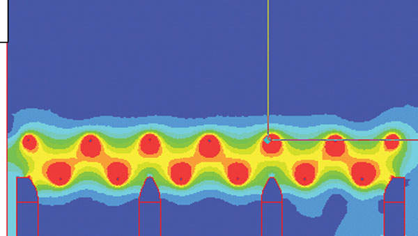
Fish protection for water intake structures
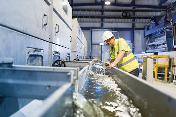
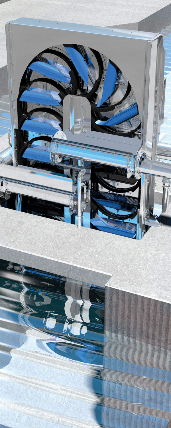
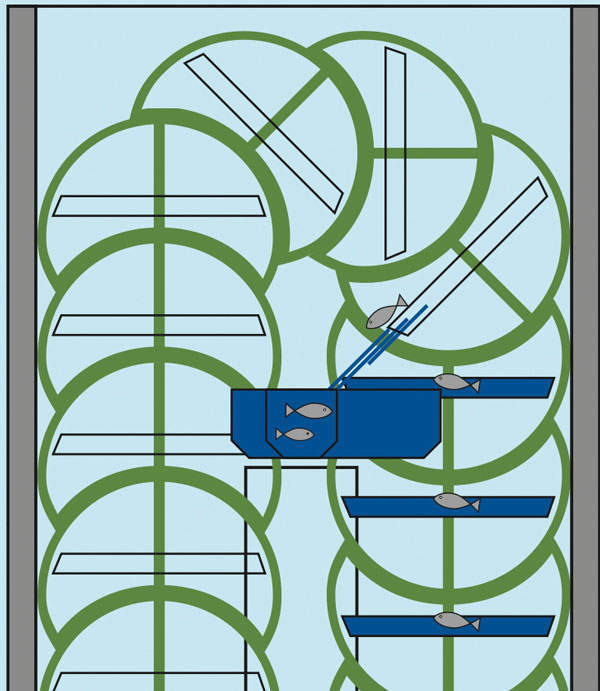
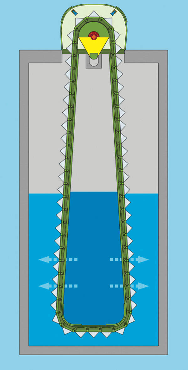
Figure 5: Computer-generated image of travelling band screen (rotating clockwise) with blue fish collection trough separated from debris trough (brown).
We use them to give you the best experience. If you continue using our website, we'll assume that you are happy to receive all cookies on this website.
ContinueLearn More X
Figure 5: Computer-generated image of travelling band screen (rotating clockwise) with blue fish collection trough separated from debris trough (brown).