Hot-cell examination of a leaking nuclear fuel rod removed in 2002 has reinforced the idea that secondary longitudinal failures can be much worse than primary failures caused by events such as debris fretting. By Göran Blomberg, Gunnar Lysell, David Schrire, Clara Anghel and Rob Schneider
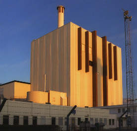
Forsmark 1 and 2 are Swedish internal pump boiling water reactors operated by Vattenfall. They have 676 fuel assemblies in the core and run 12-month fuel cycles. Forsmark 1 has suffered from fuel failures in the past, and has had frequent debris fretting failures (see Figure 1).
At Forsmark 1 fuel cycle 21 (2001-2002), off-gas indication suggested the presence of a leaking fuel rod. During a mid-cycle outage in February 2002 a leaking Atrium 10 fuel rod was successfully removed. However, offgas and levels of fission-product Np-239 (half-life 2.4 days) continued to increase, suggesting the presence of another leaker. In a second mid-cycle outage, a GE12 bundle was removed. That bundle was on its fifth cycle, had an average rod burnup of 36 MWd/kgU, and had RXA Zircaloy-2 non-liner cladding.
Within this bundle, a failed rod (F10) was found. Poolside inspection revealed that the primary failure found was debris fretting, but a 500mm-long secondary axial crack was also seen. The rod was successfully removed from the assembly and was sent to Studsvik hot cell laboratory for investigation.
Objects of hot cell investigation
There were two main objectives of the hot cell investigation. The first was to understand the consequences of the fuel failure. Part of that included a quantitative determination of the amount of uranium lost from the rod. Uranium/actinide release is important for several reasons: because so-called ‘tramp uranium’ released into the primary coolant makes it harder to detect new leakers, because its alpha activity requires enhanced radiological protection, and because plants limit the amount of long- lived alpha activity in the reactor cleanup system waste. For example, Forsmark has a plant operational target for maximum- allowed uranium release. Finally, in the authors’ previous experience, axial cracks release the most fissile material.
The second objective of the investigation was to understand the causes of the long secondary axial fuel rod split. The study was intended to establish the mechanism, and also assess the contributory role, if any, of power history and of oxidation of the cladding inner diameter and of the fresh crack surface. In the past, oxidation of the zirconium liner had been implicated in secondary axial cracking, but this rod had no liner.
Assessing the crack
To assess the amount of fuel loss, the section of interest including the long secondary crack was gamma-scanned whilst being rotated. A minimum of Cs-137 activity (as low as about 40% of the level along other parts of the crack) was found along the middle of the crack. An analysis of the Eu- 154 axial gamma scan suggests that in that region more than 50% of fuel was lost (see Figure 5, above). The researchers estimate a total of about 20g of UO2 was lost from the rod, all from the long secondary crack. The presence of Np-239 fission product detected on 6 February indicated washout of UO2 out of the fuel rod. The amount lost was highly significant, much greater than the level that today requires a forced mid-cycle outage to remove it. The amount was equivalent to the loss of three pellets of UO2 over a total length of 27 pellets.
The crack is straight through the material, but has a weaving course as it runs up the rod; these deviations are expected to have been caused by hydrides.
A point about half-way down the open crack was evaluated with an optical and scanning electron microscope to evaluate its cross-section features. An optical microscope view of the crack surface shows striations (vertical ridges) across the crack. At this point, the crack surface has a relatively thin oxide coating (2-2.5 µm), compared with oxide on clad exterior (8-12 µm) and clad interior (12-16 µm). Very near the tip of the crack, scanning electron microscopy also found relatively thin layers of oxide on the crack surface and interior compared with the clad exterior. Further enlargement of the SEM images show the extent of hydrides near the crack tip. Radial hydrides are visible near the cladding surface all around the circumference of the fuel rod. Also visible are telltale signs of delayed hydride cracking: the straight radial crack is typically seen on DHC cracks through cladding, and small hydrides normal to the crack surface that are typically seen on DHC cracks through the cladding wall.
An axial-tangential section of the crack shows that the crack propagated from the outside surface; stepwise grinding found that the angle of propagation was about 36°. SEM of the crack tip shows hydrides ahead of the crack tip (Figure 7), and thin oxides on the crack surface that do not fill the gap. That means that oxides filling the crack surface could not have forced the crack mechanically to continue to propagate.
Findings/conclusions
In summary, oxide-induced stress was found not to be the driver for the crack. There was low-to-moderate corrosion of the cladding inner surface, so it could only have had a minor contribution to a pellet-cladding mechanical interaction driving force for crack initiation/propagation. It also means that corrosion would only play a minor role in generating hydrogen in cladding on the side with the crack. However, the primary failure did allow steam to enter the fuel rod, which increased the bulk hydrogen concentration, facilitating hydriding.
The main driver of the crack was probably PCMI driven by the thermal expansion of the pellet subjected to high linear heat rates. A large axial power shape change in the area of the axial split took place during the last cycle of operation. Power suppression was not performed by the plant for any of the leakers. Also, the rod underwent an additional reactor start-up following the first mid-cycle outage when the first leaker was removed; this worsened the damage. In addition, the rod was in an assembly relatively close to deeply- inserted control blades, so there were local power changes when they were moved after the rod failed. That the rod had a relatively high burnup further worsened the situation, since it contributed to reduce the pellet-clad gap, provided fission product inventory for fission-gas swelling and degraded the rod’s thermal conductivity.
About the authors
Go¨ran Blomberg and Gunnar Lysell, Studsvik Material Handling; David Schrire, Vattenfall; Clara Anghel and Rob Schneider, Global Nuclear Fuel Americas
This material was first presented as ‘Post- irradiation examination of a failed fuel rod from Forsmark 1’ at the American Nuclear Society LWR Fuel Performance Meeting/Top Fuel 2013, 15-19 September 2013, Charlotte, North Carolina