Fidencio Mendez discusses the actual sequence of plinth excavation and concreting, the construction methods developed and the equipment used for Mexico’s El Cajon dam
The El Cajon hydro power project, with 750MW of installed capacity, includes a 188m high concrete face rockfill dam (CFRD) currently under construction on the Santiago river in the Mexican state of Nayarit. The hydroelectric project, when completed in 2006, will harness the power of one of the nation’s main waterways. The site is approximately 60km upstream from the existing 187m high Aguamilpa CFRD – to date the highest CFRD in operation in the world.
Contractor’s mobilization for the scheme began in March 2003 and river diversion was successfully accomplished in March 2004. The project master schedule calls for reservoir impoundment on 1 July 2006 with units 1 and 2 scheduled for commissioning in February 2007 and May 2007 respectively, with contract closure scheduled for August 2007. As of late March 2005, a total progress of 43% has been achieved. Major milestones this year will be slipforming of stages 1 and 2 of the concrete face up to el 340.00
The project is owned by Comision Federal de Electricidad (CFE) of Mexico. Construction is carried out under an Engineering, Procurement and Construction (EPC) contract by Constructora Internacional de Infraestructura S. A. (CIISA), a multinational consortium under the leadership of Ingenieros Civiles Asociados (ICA) of Mexico.
Project layout
The layout of the hydro scheme is shown schematically in Figure 2. The main components of the project are as follows:
• A 188m high CFRD with a 550m crest length requiring 11Mm3 of rockfill. The area covered by the concrete face slab reaches 100,000m2.
• River diversion works, including two main cofferdams and two 14m x 14m diversion tunnels excavated in hard rock located in the left bank. Tunnel No.1 is 734m long and Tunnel No. 2 is 811m long
• The generation works located in the right bank, comprising a separate concrete intake structure for each unit, two steel lined power tunnels with a 9.5m diameter each and an underground power house housing 2x375MW Francis type turbines – a surge chamber downstream from the power house and a 14×14 m inverted U shaped 310m long tailrace tunnel complete the hydraulic circuit.
• A surface spillway in the right bank, designed to discharge 14,864m3/sec. The spillway is controlled through six tainter gates.
Dam zoning and full details of the project can be found elsewhere [Mendez 20051] and [Hydropower & Dams 20032].
Plinth geology
At the lower left bank of the canyon, sound igneous rocks are exposed while at the upper left bank volcanic-sedimentary deposits are exposed defining this area as a zone ranging from medium to poor rock quality. The lower right bank close to the riverbed was also defined as an area of poor/medium rock quality and consolidation grouting was carried out intensively with primary grout holes spaced at 1.5m both ways.
In general terms, exposed rock mass shows fault zones with a North – South direction with local variations in the N20-450W or N200E direction with few structures running in the East-West direction and N450E.
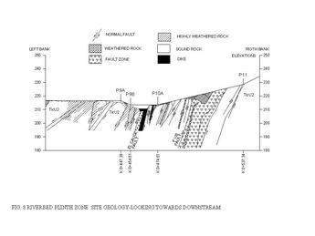
As the for the major fault zone known as ‘El Cauce Fault’, the fault runs perpendicular to the plinth axis in a N85ºE/75-85ºSE direction with its associated dyke and a semi-parallel band of severely crushed rock of about 3.5m wide (See Figure 3 and Figure 8). This major fault zone as it will be described later was not predicted during the geological exploration phase of the project. Figure 3 shows the plinth zone geology and the main geological features are briefly described below
• Fault FM1-11. – From Sta. 0+020 to Sta. 0+095 direction N-S/80°E, thickness 0.5m to 1.4m with clay filling.
• Fault FM1-12. – Diagonal to the plinth, from Sta. 0+110 to Sta. 0+130, direction N-S/75° E, thickness 1m to 2.5m with clay filling.
• Fault F II-B. – Seen on the left bank from Sta. 0+115 to Sta. 0+218, direction N-S/85° E, thickness from 0.4m to 5.5m with cemented breccias filling and partially cemented clay filling crossing the riverbed down to right bank.
• Fault F1. – Diagonal to the plinth, from Sta. 0+245 to Sta. 0+270, direction N 15° W/75° SW, thickness from 0.9m to 1.25m with partially cemented breccias filling and clay.
• Fault FVII.- Diagonal to the plinth, from Sta. 0+680 to 0+703, direction N 30° W/75° NE, forming a fractured and faulty band with thickness up to 12 m. The main zone of the fault has a thickness of 0.3m to 2.5m with breccias and clay fillings.
Plinth conception
The plinth, together with the perimetric joint waterstop, is the watertight connection between the foundation and the concrete face [Cooke3]. Following modern trends, the El Cajon CFRD adopted the design of an external constant plinth of 4.5m wide conceived as a reinforced concrete structure dowelled on the rock foundation, complementing with an internal slab (internal plinth) of varying length to guarantee an adequate hydraulic gradient, the undowelled thin internal slab has a maximum length of 13m in some areas. To facilitate construction, the plane of the internal slab was excavated in the same plane of the external plinth.
The cross section of the plinth is shown in Figure 4. The main condition presiding definition of plinth width was erodibility of the foundation material. Plinth width was defined following guidelines described elsewhere [Marques Filho and Machado 20004]. The plinth is continuously reinforced with no waterstops between individual concrete pours.
The perimetric joint design is fully depicted in Figure 5. Technical specifications call for the use of a copper bottom waterstop and an upper copper waterstop throughout the length of the perimetric joint. In addition, and as it was done at Aguamilpa CFRD, directly over the perimetric joint a protective zone of cohesionless fines ( fly ash) will be placed which can be washed into the joint should excessive displacement occur – the fly ash is contained within a galvanized steel half barrel lined with a geotextile. The concept behind the use of the steel half barrel has been described elsewhere [Montañez 19925].
A single line grout curtain up to a depth of 77m with adjacent upstream and downstream consolidation grouting is provided below the plinth. Grouting is carried out using the GIN method [Lombardi, G., and Deere, D., 19936].
Plinth construction strategy
The construction strategy was set as follows:
• Mobilisation, access roads to strategic points of plinth zone, abutment stripping, diversion construction, plinth construction above river water level. This stage is completed.
• River diversion, cofferdams, riverbed excavation, and plinth construction at the riverbed, grouting. This stage is also completed.
• Completion of plinth excavation and concreting in the right bank. At the time of writing, plinth excavation is complete and concreting activities above el 322 are well underway.
Planning and construction of access routes
A network of permanent and temporary access roads were planned and developed to facilitate construction at different stages of project construction. From this network, branches leading to strategic points of the plinth zone were developed as shown schematically in Figure 6.
Plinth excavation
Plinth hard rock excavation in the left bank began at the beginning of the contract simultaneously with river diversion works. Plinth excavation was carried out by drill and blast with controlled blasting operations. All stages were drilled using a fleet of crawler mounted Hydrotracks Ranger 500 from Tamrock. Drill steel was 75mm round, in lengths of 3.1m; the drilling speed was about 35m/hour for each drill rig. Blastholes were charged with a combination of ANFO and Hydrogel. For each blast, a number of stages of delay were used in firing the charges, with initiation being achieved by NONEL detonators connected to a detonating cord line. For benching, the pre-splitting technique was carried out systematically to minimise stress and fracturing of the rock beyond the perimeter and to provide smooth, even rock surfaces. Pre-splitting was performed well ahead of the main blast and a maximum of 25kg of explosive per delay was specified for benching.
Stage 1 – Excavation from P1 to P3
Due to the local flat topography, excavation was a straightforward operation. From P1 to P3 design called for a reinforced concrete gravity wall connecting the plinth with the top left abutment at crest level, thus excavation to reach foundation levels was easily performed with blasted rock being loaded into articulated off-road Terex TA30 trucks by a Cat 330 crawler mounted backhoe. Hauling was performed by the off-road articulated trucks travelling along access road No.1.
Stage 2 – Excavation from P3 to P6
Local topography shows a steep incline left abutment therefore benching proceeded from top down with blasted rock being pushed down the hill by dozers to a loading platform at el. 335.00 where a Cat 330 crawler mounted backhoe mucking into articulated off-road Terex TA30 trucks travelling along access road No.2.
Stage 3 – Excavation from P6 to P7
Local topography still shows a steep incline abutment, and benching proceeded from top down with blasted rock being pushed down the hill by dozers to a loading platform at el. 268.00 where a Cat 330 crawler mounted backhoe mucked into articulated off-road Terex TA30 trucks travelling along access road No.3.
Stage 4 – Excavation from P15 to P12
Benching proceeded from top down concurrently with power intake channel excavation, with blasted rock being loaded at loading platforms located at different levels within the power intake channel zone by a Cat 990 front-end loader mucking into 50 ton off-road Cat 773E. Blasted material from the upper benches was hauled by off-road trucks ramping out of the power intake channel and then travelling along the network of temporary access roads designed to excavate the power intake channel and the spillway while the lower benches were mucked out using access road No.5. Blasted rock was hauled and disposed at stockpiles in preparation for its use at the dam embankment.
Stage 5 – Excavation from P12 to P11
Local topography shows a steep incline in the right abutment, and benching proceeded from top down with blasted rock being pushed down the hill by dozers to a loading platform at el.229.00 where a Cat 330 crawler mounted backhoe mucked into articulated off-road Terex TA30 trucks travelling within the dam body and then along access road No.4.
Stage 6 – Excavation from P8 to P9
Here again in the left abutment, the steep incline abutment continued, and benching proceeded from top down with blasted rock being pushed down the hill by dozers to a loading platform at el.222.00. Mucking and hauling were performed by a combination of a Cat 330 crawler mounted backhoe and articulated off-road Terex TA30 trucks traveling along the access road No.4.
Stage 7 – Excavation from P7 to P8
Excavation procedures were similar to Stage 3.
Stage 8 – Excavation from P9 to P10A
This is the riverbed zone, conventional benching techniques were applied with blasted rock being loaded by a Cat 330 crawler mounted backhoe mucking into articulated off-road Terex TA30 trucks travelling along access road No.4.
Stage 9 – Excavation from P10A to P11
Located still within the riverbed zone and for a number of reasons, namely the presence of the fault zone now known as ‘El Cauce fault’ and its associated delays design -wise to name just a few, this was the last stage. Local topography shows a steep incline in the right abutment, and benching proceeded from top down with blasted rock being pushed down the hill by dozers to a loading platform at el.229.00 where a Cat 330 crawler mounted backhoe mucked into articulated off-road Terex TA30 trucks travelling within the dam body and then along access road No.4.
A step by step summarised excavation sequence can be seen in Figure 7 and table 1 shows a summary of excavation quantities, work periods and access routes for each stage. Excavation was carried out using the following pieces of equipment: eight Off-road Terex TA 30 articulated dump trucks ( shared with other areas); three Hydrotrack Ranger 500 Series 2 from Tamrock; two Cat 330C Crawler mounted backhoe; two Cat 966F Front-end loaders; three Cat D8R dozers
Major geological fault
As mentioned before, once the river was diverted, riverbed clean up and excavation began immediately. When riverbed plinth excavation reached design elevations, the project met a significant geotechnical challenge on the riverbed zone, where a major geological fault now known as ‘El Cauce Fault’ was exposed (See Figure 8). To cope with the troublesome material, a multidisciplinary engineering team backed by international CFRD experts analysed a number of options to deal with this unforeseen geological condition and after a long debate as to what to do, a consensus was finally reached and a decision was made because time was of essence. Details of actual fault special treatment and plinth re-alignment developed to suit field conditions are shown in Figure 9.
Restructuring the plinth foundation at the riverbed zone included concrete backfilling up to el. 211 as a first stage, the idea being to fill out the very irregular-shaped cavity and to have a horizontal working surface in preparation for subsequent work to be done. In order to secure the concrete block, 12m long dowels were installed crossing the fault zone both ways to anchor the concrete block on sound rock at either side of the fault zone. In addition, complimentary instrumentation was installed in order to closely monitor this area during the operation phase of the dam; additional installed instruments were two extensometers and two electric piezometers.
After concreting to el. 211, a systematic pattern of 38mm-diameter dowels at 1.5m spacing both ways was drilled and installed, followed by rebar placement and a second lift of concrete backfill up to el. 214 as shown in Figure 9. Embedded in this second lift were the drainage steel perforated pipes to handle inverse seepage as described elsewhere [Mendez 20051]. When the above mentioned works were completed, the work in the structural plinth itself started.
Concreting the plinth
The concrete poured had a compressive strength of 250 kg/cm2 with a maximum aggregate size of 38mm and water to cement ratio of 0.5. Slump was in the range of 100mm to 120mm. Special foundation treatment was done following the criteria described for Salvajina CFRD [Hacelas, J. E., and Marulanda, A., 19897]; where seams of weathered, crushed rock, clay filled faults were present at foundation level the altered material was excavated to a depth of three times the width of the seam and backfilled with concrete. Particular attention was paid to those features that crossed the plinth foundation transversally.
Phase 1 – Concrete from P5 to a point between P7 and P8
Plinth design in this area calls for a horizontal plinth between points P5 and P6. This particular part of the plinth seemed a straightforward piece of work to do, therefore in order to train all crews involved, i.e. rebar, carpenters, copper waterstops, concrete placement, etc., this portion was chosen as the first pour. The 5m3 concrete truck mixers reached the area via access road No.2 and unloaded the mix into a Putzmeister BSF 36Z 12L mobile concrete pump equipped with a telescopic boom parked at a temporary platform at el.335 near point P6. From this platform concrete was pumped to all pours of the plinth located between points P5 and P7. Curing was done applying plastic membrane and then covered with a wet mat made of natural fibers. The mat was wet at all times for at least seven days.
Phase 2 – Concrete from P2 to P5
Concrete was delivered to the pour zone using access road No.1. The mobile concrete pump was set at a temporary platform located at el 385 in the vicinity of point P2 and from there fresh concrete was pumped downwards. Placing of concrete proceeded upwards from points P5 to P4 where a construction joint was left. At a later stage, the remainder pours from points P4 to P2 were performed with concrete being pumped and placed as in the previous pour.
Phase 3 – Concrete from a point between P7 and P8 to a point between P8 and P9
Concrete was delivered to the plinth zone using access road No.3 for pours located between points P7 and P8 and for some pours located between points P8 and P9. The mobile concrete pump was set along access road No.3 at el 268 at the vicinity of point P8 and from there, fresh concrete was pumped. Pumping of concrete proceeded upwards for pours located between points P8 and P7 and downwards for pours between points P8 to P9.
Phase 4- Concrete from a point between P8 and P9 to P11 (riverbed)
This is the riverbed plinth. Concrete was delivered to the riverbed plinth zone using access road No.4.The mobile concrete pump was set on a temporary working platform upstream of the plinth zone at el 222 for all pours and from there, fresh concrete was pumped. For each individual pour the mobile concrete pump was relocated accordingly along the working platform.
Phase 5-Concrete from P11 to a point between P11 and P12 (Riverbed/Right bank)
This is still part of the riverbed plinth and it is also the start of the right bank plinth. Concrete was delivered to the plinth zone using access road No.4 at first and then via a branch built within the dam body. The mobile concrete pump was set on a temporary working platform located on Material 3B zone downstream of the plinth zone at el 222 for all pours in this portion and from there, fresh concrete was pumped upwards. For each individual pour the mobile concrete pump was relocated accordingly within the dam body temporary ramps and platforms.
Phase 6- Concrete from a point between P11 and P12 to P12 (right bank)
Concrete was delivered to the plinth zone using access road No.5. The mobile concrete pump was set on the invert of the power intake channel at el 322 for all pours in this portion and from there, fresh concrete was pumped downwards.
Phase7- Concrete from P12 to P13 (right bank)
Performed similar to Phase 6; fresh concrete being pumped upwards from el. 322 for all pours in this portion.
Phase 8- Concrete from P13 to P15 (right bank)
This was the last stage and concrete was delivered to the pour zone using the permanent access road to the top of the power intake control zone at el 396. The mobile concrete pump was set at the platform located at el 396 in the vicinity of point P15 and from there fresh concrete was pumped downwards. Placing of concrete for individual pours proceeded upwards from points P13 to P15.
A step by step summarised concrete works sequence can be seen in Figure 10 and table No.2 shows a summary of concrete quantities, work periods and access routes for each phase. For the plinth, rebar was installed with a rate of rebar to the concrete of 105kg/m3. Figure 11 shows progress in the plinth right bank and in the upstream zone of the CFRD as of mid February 2005.
It is worth mentioning that the pace of concreting the plinth was governed by progress in the embankment placement, the basic idea was to keep the concrete operations ahead enough in order to avoid interferences with rockfill placement.
Actual production rates recorded for any individual pour of the plinth with a length of 40m to 45m, say from Sta. 0+150 to Sta. 0+195 is one week with crews working around the clock, for rebar placement, waterstops installation, form erection and pouring concrete. Plinth individual pours were systematically in the range of 40 to 45m in length with no PVC waterstops between them. Concreting the plinth was carried out using the following crews allocated in two shifts: 15 workers for rebar installation; 11 workers for formwork erection and perimetric joint details (waterstops, etc.); 25 workers for concrete placement and miscellaneous tasks
Conclusions
Despite its size, the El Cajon CFRD has a tight construction schedule. In order to cope with the demand for rapid construction imposed by the EPC contract it was essential to establish rapid construction methods to secure the project master schedule. An important consideration in scheduling the plinth construction was access. Rapid progress has been achieved as a result of careful planning of the permanent and temporary access roads connecting to strategic points at the plinth zone.
Another key consideration was the careful selection of the right construction equipment in particular the use of the articulated off-road Terex TA 40 dump trucks and the Hydrotracks for the drill and blast operations during plinth construction. Only brand new, modern heavy construction equipment was used.
El Cajon CFRD and hydro power project represents the fastest construction operation ever achieved in Mexico for a large scale hydroelectric project. It is hoped that the material presented here will facilitate the planning, design and construction of the plinth for CFRD’s of similar scope.
Author Info:
Fidencio Mendez, Federal Commission of Electricity (CFE), Mexico