Most nuclear power plants pump in large amounts of water from a river or bay for cooling, either on their own (once-through), or in combination with cooling towers. But there are population centres in need of power that lack such water resources. In one such case, Palo Verde’s three-unit power plant takes cooling water from an unlikely source: treated effluent. The model is being studied by potential power plant customers such as Jordan. By Will Dalrymple
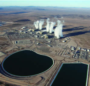
At the Palo Verde Nuclear Generating Station, water treated at Arizona’s largest wastewater sewage plant is piped 36 miles to a treatment plant and then into on-site reservoirs. From there, it feeds the plant’s tertiary cooling loop that runs through condensers under the turbogenerator, through cooling towers, and back again, until it is super-concentrated and diverted to evaporation ponds.
There are many factors that need to be considered with such a novel method of cooling, including: the size of the water source and its effluent chemistry, materials for construction of the waste water treatment plant and the pipeline, the property required for huge storage reservoirs, as well as numerous environmental and permitting considerations.
"What with the water quality sent to the evaporation ponds, how many acres you need, the rate of evaporation, which changes with the water concentration, so as the total dissolved solids builds evaporation slows, and mapping that with liner issues…This isn’t for the faint of heart. You have to know that this is something that you’ll deal with for the length of the plant," says Robert Lotts, director of Arizona Public Services’ water resources plan, and a 27-year veteran of Palo Verde’s Water Reclamation Facility (WRF).
A model for elsewhere
After hosting a Jordanian delegation in 2010 at Palo Verde, Lotts travelled to Amman, Jordan (population 2.8 million) in December 2011 where he met the chairman of the Atomic Energy Commission, and evaluated the quality of the potential input wastewater. His verdict: "It is actually really similar. The water quality of the wastewater treatment is similar to ours — a little more concentrated, because the per capita water use is less. Some of the species that I looked at were a little more concentrated and total dissolved solids is a little higher, but all in all, they are pretty comparable in wastewater terms. They’re going to be basically doing the same thing as us."
When asked if this system can work anywhere, provided the city is large enough and the treatment is good enough, Lotts replies: "That’s my opinion. I know it can be done."
Lotts outlines his advice about how to arrange a water treatment system for a nuclear power plant new-build project. "Number one is building a small-scale facility to understand what your quality needs are; you are looking at the footprint of the plant, and designing a treatment system with some margin so that if you do lose a piece of equipment or it fails, there is some redundancy.
"Then you need to determine what your storage capacity needs are, and staffing. Where will you get people that are trained and knowledgeable? What training programmes do you have? We have in our staff, an entire maintenance staff with mechanical, electrical, I&C, engineering [expertise]; all of the engineering fields are represented. You need chemists for the plant, and plant operators. The control system for the plant is mostly run through a computer, so you need computer engineers. Today our staff is about 110. We’ve been as high as 170."
But he admits that wastewater has rarely been used for cooling because of the difficulty, and the expense. "It is easier to build a power plant on a freshwater lake, or a river, and do once-through cooling. You don’t have the load of the wastewater plant," Lotts says, adding, "There is a cost associated with this kind of treatment facility. The staffing, the chemicals, and everything else. But as time goes on, if you believe in climate change or not, rivers may become less sustainable, their flows less reliable and dependable, and different environmental regulations…they may change how you think about it."
Sewage offtake
Fresh water in the Phoenix, Arizona area comes from the Verde, Salt and Colorado rivers. After it is used by the two million people living in the area, it reaches the 91st Street water treatment plant in Phoenix. This plant, built before Palo Verde but expanded several times since then, actually serves four areas in the metropolitan Phoenix area: Phoenix, Scottsdale, Mesa, Tempe and Glendale, although the city of Phoenix owns more than 50%. Its rated capacity is 204 million gallons/day, but its operational amount is 130-150 million gallons/day. Another treatment plant nearby, capacity 17 million gallons/day, serves the city of Tolleson. Both plants carry out primary and secondary water treatment: primary sludge settling and separation, and degradation of the biological constituents of sewage.
Normally, wastewater treatment plants pump the treated effluent back into a river. At this plant, a 114-in (3m)-diameter pipe diverts up to 90,000 million gallons/day toward Palo Verde; another pipe also takes up to 6 million gallons/day from Tolleson. (Other effluent streams go to irrigation in Buckeye, Arizona, and an artificial wetlands area next door, and the Salt and Gila Rivers). The utility consortium that owns the three-unit Palo Verde Generating Station buys the water from the city; it is authorized to take up to 24 billion gallons/year, or an average of 65 million gallons/day, but uses more like 21-22 billion gallons/year (and up to 2.2 billion gallons/year from Tolleson). It pays based on a unit of an acre-foot, 326,000 gallons/year or 1233.5 m3, in a price that is escalated per year.
Palo Verde is a 12000 MWt station based on three CE System 80-based two-loop PWRs. Its largest stakeholder is Arizona Public Services (29.1%), but it is also owned by Salt River Project, El Paso Electric, Southern California Edison, Public Service Co. of New Mexico, Southern California Public Power Authority, and L. A. Dept. of Water & Power.
Water flows 100ft downhill inside the buried pipeline for about 28 miles (6 miles at 114in diameter pipe, 22.5 miles at 96in diameter pipe) until it reaches the Hassayampa Pumping Station, which pushes it 125ft uphill the remaining eight miles to the site treatment plant in a 66in-diameter pipe.
Every three years, during an outage, the water flow is stopped, and one of the reservoirs is allowed to drop to 50%. Then the water is stopped and the pipeline is inspected, visually and with remote field eddy-current testing. A thin steel cylinder separates inner and outer concrete shells. Pre-stressing wires wrap around the outer concrete shell, which is covered by mortar. Defects are monitored, analysed and planned for repair. A database tracks the condition of each of the 8500 prestressed concrete pipe segments, categorised and prioritised for maintenance.
Treatment
The Palo Verde Water Reclamation Facility (WRF), pictured below, prepares the water for use in the power plant. "Understanding the water quality issues that you see from the wastewater treatment plant is a primary concern." Lotts says. "You can perfect the tests on a small scale, and use the small-scale treatment plant to see the effectiveness of the plant on the hardness of the water, what the chemical dosage rates are going to be, and then you are looking at chlorides and sulphides, whose constituents might combine to form scale, silica. You are looking at chloride, and what kind of impact it will have on materials of construction. A lot of evaluation went into this, not just the quantity of water and the amount of treatment, the compatibility of materials going to build the plant with, so that it didn’t have a negative impact on metals."
The WRF cleans the water in three stages (see diagram). The first stage treatment is a biological reduction of ammonia from the influent by trickling the effluent down over biological growth maintained on plastic media. The second part of the treatment is lime soda softening to reduce hardness. Slaked lime is added to the first stage solids contact clarifiers, elevating the pH to 11.2, causing scales to settle to the bottom as a heavy sludge. This sludge is raked to the middle and pumped out of the system for disposal. In the second stage solids contact clarifiers, the pH is lowered to 10.2 by adding CO2 gas which, with addition of soda ash, precipitates calcium and further reduces water hardness. The final stage of the treatment plant is gravity filtration. After further adjusting pH to 9.2, the treated effluent is sent to 24 filters with layers of anthracite coal over sand. They act as a polisher, to reduce suspended solids (such as calcium) in the treated effluent.
| Constituent | Influent (ppm) | Effluent (ppm) | Circ system (ppm) |
|---|---|---|---|
| Alkalinity (as CaCO3) | 161 | 42 | 30-60 |
| Calcium (as CaCO3) | 168 | 87 | 500-2500 |
| Magnesium (as CaCO3) | 133 | 33 | 100-750 |
| Silica | 18 | 4 | <155 |
| Phosphate | 10 | 0.3 | <10 |
| Total dissolved solids (TDS) | 1015 | 1001 | <30,000 |
A company document says that effluent quality is controlled based on the calculated solubility of constituents, to maximize water use while minimizing treatment cost. Solubility indices were established from extensive testing to determine scale potential in the cooling water system. The solubility index for calcium carbonate, fluoride, phosphate and sulfate are derived from real-time data to provide treatment parameters for operation of the facility.
Reservoirs
Water is pumped from the WRF to the adjacent reservoirs at the Palo Verde site. There was originally only the one, but a second was dug 10 years ago when leaks were discovered in the original liner; the first reservoir was drained, reshaped slightly and relined. Now, both have 60mm-thick inner and outer HDPE (synthetic rubber) layers with a netting layer in between, which runs to a sump and helps indicate the presence of a leak. The liners have a 20-year expected lifetime.
The presence of a leak was significant not only because of the loss of cooling water, but also because of the way the plant’s environmental permits work. The liner marks the boundary of the plant’s environmental permit. Although that required the utility to reline the main reservoir to adequately isolate it from the environment, this approach to permitting also gives it much greater flexibility in adjusting the water chemistry over short time periods to reach an optimal system for turbogenerator condenser performance. Had the utility set a permitting boundary at the cooling canal, it would need to apply to the agency in order to change its composition.
In Arizona, water quality changes based on the levels of the reservoirs that feed population centres, in which total dissolved solids and concentration of chlorides can increase as water levels fall, which requires different levels of response for calcium or magnesium.
The two reservoirs together total a billion gallons: 788,300,000 in the main, 85-acre (34.4 ha) kidney-shaped reservoir, and 372,000,000 in the other 50-acre squarish reservoir. Loss of water due to evaporation is significant in this climate, which is hot and very dry. Temperatures range from near freezing (32°F) in winter to up to 120°F (49°C) in summer. As a consequence, the upper layers of water heat up. Lotts estimates that over a year the reservoirs lose about 5% of their volume to evaporation: 60-72 inches per year, or 3250-3900 acre-feet in total, compared to 70,000 acre-feet used (71,111 in 2012, which corresponds to 740 gal/MWh).
Despite the temperature variation at its surface, down towards the bottom of the reservoir, where the water intake pipes are, the water holds its temperature within five degrees either side of 25°C. The reservoirs also feed the nearby 1060 MWe Redhawk combined-cycle natural gas power plant, 1.4 billion gallons of water/year to feed a 42-acre reservoir (cooling water use: 298 gal/MWh).
Although the reservoirs are large enough to keep the water temperature constant, they are not large enough to use as a heat sink for the entire plant in a once-through cycle arrangement. Instead, three forced-air cooling towers are used. The environment is so hot and dry that natural-draught cooling towers would need to be an immense 600ft high to work properly, Lotts says, owing to the low dew point of the dry desert air. He admits that station operation during the hot summer months lowers the efficiency of the cooling towers, increasing turbine back pressure, which does lower the reactors’ efficiency.
It takes the treatment plant about a week of pumping to fill the main reservoir up, based on 90 million gallons per day. Each of the three reactor units take between 60-65 million gallons/day in winter and 80-85 million gallons/day in summer when operating, which means that without any intervention they would drain the reservoir in less than 12 days, worst case. Part of the decisionmaking involved in design of the facility called for a reservoir volume of 30 days’ worth of cooling water, but preventative maintenance programmes of the water treatment facility, including the pipeline, the pump station and some equipment in the treatment plant proper, have increased the plant’s confidence of the reliability of the system, and so reduced the interval. (The size of the reservoirs were then determined based on the equipment mean time-to-failure and mean return-to-service based on the equipment’s PM schedule).
| Input | Output | |
|---|---|---|
| WWTP | 74700 | |
| Site wastewater | 22 | |
| Groundwater | 2175 | |
| Reservoir evaporation | 700 | |
| Redhawk | 3000 | |
| Water vapour | 70050 | |
| Blowdown | 2920 | |
| Sent to evaporation ponds | 231 | |
| 76897 | 76901 |
Although chlorine is added to the water in the treatment plant, the reservoir is too large to maintain a chlorine residual, so there are some nutrients present in the reservoir. That is why emergency fire water supplies draw not from the reservoirs, but from the 1000-feet deep wells drilled down to an aquifer to supply fresh drinking water and deionized water for the reactors and steam generators on the site (2000 acre-feet/year, or about 3% of total site use). Biological fouling might impede the flow of water in the fire header were it to draw from the reservoir.
Depending on the time of year, the rate of water injected from one or both reservoirs as makeup to compensate for evaporative loss varies between 13,500 gal/min-18,500 gal/min, per unit. That water is injected into the cooling water circulation canal. That canal feeds the tube side of the condenser at a rate of 580,000 gal/min. As the water flows, it takes waste heat from the reactors’ secondary loops. From the condenser, the water now heated to 48.2°C travels to the top of one of three forced-air cooling towers. Each tower receives about 195,666 gal/min of water, of which 14,000 gal/min is lost in evaporation. The rest trickles down through the structure to the base, from where it returns at 30.7°C to the circulation canal. After some 20-25 such circuits (the five-year average is 23.3 cycles), the water has become progressively more concentrated until its composition resembles seawater (air quality standards limit TDS to 30,000 ppm).
In the circulation canal, a blowdown line draws off a relatively small amount of the water depending on canal water chemistry (chloride concentration or TDS, and scale-forming compound solubility) of about 600 gal/min/unit, and discharges it to three rectangular evaporation ponds totalling 650 acres (263 ha), where its journey ends. The amount of water siphoned off is carefully controlled to maintain an overall water balance on the site: the average five-year blowdown loss was 3060 acre-feet/yr (997 million gal). Lotts said that it would be possible to use brine concentrators to reuse some water, but, over the long term, evaporation ponds were chosen because they were the least expensive approach.
The condenser pipework is titanium (supplied by Valtimet), which has proven to be extremely resilient. Condenser maintenance is actually very simple, consisting of an inspection and vacuum testing during outages. "Titanium has worked great. It is much more resistant than some stainless steel alloys," Lotts says. Condenser tubesheets are aluminium-bronze.
The total load of the water supply system and water treatment plant, in summer, is 6 MW.
What is the most environmentally-friendly way? |
|
The Palo Verde Nuclear Generating Station consumes 100% of the water that it takes from the 91st Street wastewater treatment plant. It does not return any water back to the community, although it could, Robert Lotts says. It could be treated again and returned to the ground, but because people are not ready for direct reuse, it will not be returning to the water supply. "But we need water, and this is a huge plant, and the other thing Palo Verde brings is revenue; it is a very large positive financial benefit in revenue for the state of Arizona." Lotts says that it is difficult to understand whether the Palo Verde approach is more or less environmentally-friendly than other power plants with a once-through cooling arrangement. On one hand, it only uses water that has been used already; but on the other hand, it does not put any water back. A once-through plant can return all the water that it has taken out, but it has raised the temperature of that water, so that when it returns it will be more prone to evaporation, Lotts says. "We don’t have a good handle on what the consumptive use is. In theory it is x, but how do you know?" |